FLOATING BODY STRUCTURE ABLE TO GENERATE ENERGY BY OSCILLATING UNDER THE EFFECT OF THE WAVE MOTION
Technical Field
The system concerns a floating body structure, which is able to exhibit limited controllable oscillation under the influence of the waves and similar water motions forming on the sea and similar masses of water and which involves the possibility of using said motion for the purposes of energy conversion.
Description of the Figures
Figure 1. A side view of the floating body with the functional members thereof in assembled stateFigure 2. A sectional view of the floating body
Figure 3. A sectional view of the floating body
Figure 4. A view of the weight with the attached outer weight member and weight connection member
Figure 5. A sectional view of the floating body
Figure 6. A sectional view of the floating body in a state including the floating body fixing member
Figure 7. A view of the platform surface
Description of the Reference Numerals in the Figures
- Floating body
- Floating body lower surface
- Weight motion surface side barriers
- Weight motion surface
- Weight
- Outer weight member
- Weight connection member
- Connecting shaft
- Balancing weight
- Bearing feet
- Platform surface
- Tension unit
- Coupling unit
- Motion shaft
- Motion shaft bearing
- Guide pulley
- Weight fitting
- Floating body fixing member connection
- Floating body fixing member
- Gap
a. Motion surface inclination angle
M. Metacenter point
K. Floating body lower midpoint
B. Flotation center
G. Center of gravity
X. Horizontal axis/p>
Description of the Invention
The invention concerns a floating body (1) with structure suitable for floating on the water, wherein said floating body comprises a weight (5) capable of moving through 360˚ in any direction on the horizontal plane, i.e. capable of moving through 360˚ along the horizontal axis (X), and wherein said floating body is able to generate energy by oscillating as a result of the wave motion.
Said floating body (1) is manufactured from the materials with structure suitable for floating on the water. The floating body (1) embodies a floating body lower surface (2). The floating body lower surface (2) constitutes the bottom portion of the structure in contact with water.
The floating body lower surface (2) is equipped with the weight motion surface (4) where the weight (5) is to move and the weight motion surface side barriers (3). In this way, the weight (5) is able to move on the weight motion surface (4) in a manner restricted by the weight motion surface side barriers (3).
Referring to Figure 4, the weight (5) is in the form of a ball and is provided with an outer weight member (6). The outer weight member (6) is designed in the form of an outer collar so that it will allow the free rotational motion of the weight (5) while keeping the same within itself. Owing to this structure, the weight (5) is able to freely rotate within the outer weight member (6) wherein said weight may be held by the collar structure without falling out.
In order to enable the weight (5) to move independently within the floating body (1), said weight (5) is provided with the weight connection member/s (7). The weight connection members (7) may take the form of a rope or chain.
Referring to Figure 4, the weight connection members (7) are associated with the outer weight member (6). The outer weight member (6) includes the weight fittings (17) on its surface. The weight connection members (7) may be connected to the weight fittings (17).
Referring to Figure 1, the weight motion surface side barriers (3) comprise the guide pulleys (16) on the surface thereof. The weight connection members (7), which are connected with the outer weight member (6), are able to transfer, via the guide pulleys (16), all the motions of the weight (5) on the weight motion surface (4) to the upper portion.
Referring to Figure 1, the floating body lower surface (2) is an outer surface form consisting of a combination of the pieces in the form of an arc section, with either different or identical structure. According to an embodiment of the invention, this structure is in the form of a ball segment.
Owing this geometric structure, it is possible for the waves reaching from any direction to act by the same extent and magnitude upon the water volume in which the floating body lower surface (2) is submerged.
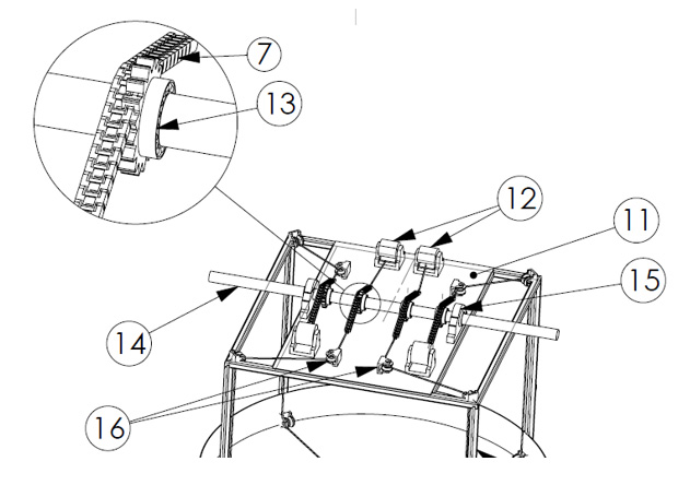
Referring to Figure 1, the platform surface (11), disposed on the bearing feet (10), is positioned on the weight motion surface side barriers (3). The platform surface (11) embodies the members required for the conversion of the motion energy generated by the motion of the weight (5).
The weight connection members (7), which are connected to the weight (5) and which are transferred to the upper portion of the weight motion surface (4) by means of the guide pulleys (16) on the weight motion surface side barriers (3), are transferred to the guide pulleys (16) contained within the platform surface (11). The weight connection members (7), which are transferred by means of these guide pulleys (16), are guided towards the motion shaft (14). The motion shaft (14) is equipped with the transmission members capable of transmitting the motion received from the weight connection members (7) to said motion shaft (14) in the form of circular motion.
The circular motion generated on the motion shaft (14) may be coupled to various energy conversion mechanisms in order to be brought into a state suitable for being converted into the electrical energy and for being transmitted.
The weight connection members (7) transferred from the guide pulleys (16) to the motion shaft (14) are fixed to the tension unit (12) at another end section thereof. The tension unit (12) is an apparatus, which is able to release the weight connection member (7) or keep the same in a tensed state as the occasion requires.
According to an embodiment of the invention, the connection members are in chain form either over their entire structure or over the portion thereof in contact with the transmission members. Accordingly, the transmission members are in the form of a gear so that they can receive the motion from the chain.
Referring to Figure 7, the transmission members are defined by a coupling unit (13) that has the form of a gear.
In order for the motion shaft (14) to be able to provide the above-mentioned motion, said motion shaft (14) is associated with a motion shaft bearing (15) via at least two points thereof.
The floating body lower surface (2) comprises at least one connecting shaft (8) positioned at the bottom portion of said surface that is submerged in the water. Said connecting shaft (8) is equipped with at least one balancing weight (9). The connecting shaft (8) and the balancing weight (9) connected to said shaft have a rigid structure in terms of the connection type, wherein they comprise a fixed part of the floating body (1) and move in conformity with all the oscillating motions of the floating body (1).
In order to fix the floating body (1) at a certain position on the mass of water and in order to support the oscillating motion, said body (1) is associated, via at least one point thereof, with the floating body fixing member (19) by means of the floating body fixing member connection (18).
The floating body fixing member (19) may be formed by an anchor or by a mass with weight able to retain the floating body at a certain section of the mass of water.
At least one gap (20) is formed in the bottom portion of the floating body lower surface (2) that is submerged in the water. This gap (20) is a clearance with a form able to enclose the floating body fixing member connection (18).
Referring to Figure 6, the gap (20) is a bottom clearance in conical form.
The floating body (1) is a mass, which is able to perform oscillation in a state connected to the floating body fixing member (19) by means of the waves and the similar motions of the mass of water. It is intended to prevent the floating body fixing member connection (18) from contacting the floating body (1) to the maximum extent possible during the oscillating motion. Each contact of the floating body fixing member connection (18) with the floating body (1) reduces the performance of the oscillating motion. Owing to the gap (20) formed, the floating body fixing member connection (18) will be able to perform oscillation with minimum contact with the floating body (1) during the oscillation of the floating body (1).
Referring to Figure 6, the floating body fixing member connection (18) is fitted to the floating body (1) at a location that is as close as possible to the flotation center (B) point. Said fitting is provided via a point that could correspond to a position between the floating body lower midpoint (K) – center of gravity (G).
The structure and shape of the gap (20) are designed in a manner suitable for fitting the floating body fixing member connection (18) at a location as close as possible to the flotation center (B).
According to an embodiment of the invention, the floating body fixing member connection (18) is connected to the floating body (1) via the flotation center (B). In this case, the flotation center (B) is formed at the apex of the gap (20).
Owing to this structure described above, upon the oscillating motion, the floating body fixing member connection (18) is able to move within the gap (20) with minimum contact with the walls of the gap (20).
The metacenter point (M) is a point on the vertical axis passing through the floating body lower midpoint (K), flotation center (B) and the center of gravity (G), being on the sectional axis when the floating body (1) is stable. The metacenter point (M) is a point positioned above the center of gravity (G) on the floating body (1). This point changes according to the design of the floating body (1).
The metacenter point (M) may be defined as the point where the line drawn perpendicularly from the center of gravity (B) of the submerged object, which would result when the floating body (1) is inclined, to the water surface intersects the axis passing through the floating body lower midpoint (K), flotation center (B) and the center of gravity (G) when the floating body (1) in stable condition.
The floating body lower midpoint (K) defines the midpoint of the floating body lower surface (2).
The flotation center (B) defines the flotation center of the floating body when the system is positioned in the mass of water.
The center of gravity (G) defines the center of gravity of the floating body (1), i.e. the entire system.
The motion surface inclination angle (a) defines the angle formed between the weight motion surface (4) and the horizontal axis (X). For the case where the motion surface inclination angle (a) is 0˚, the weight motion surface (4) may be designed in the form of a plane.
In cases where the motion surface inclination angle (a) is greater than 0˚, the weight motion surface (4) is in the form of a conical surface that is inclined inwards. The inward conical form of the weight motion surface (4) may change according to the value assumed by the motion surface inclination angle (a).
In case the motion surface inclination angle (a) is greater than 0˚, the weight motion surface (4) has the structure of a cone designed with a form where the center is more depressed than the sides.
According to the invention, the motion surface inclination angle (a) may be arranged such that it may take values equal to and greater than 0˚. The frequency of the oscillating motion of the floating body (1), wave intensity on the water mass and the ambient conditions may be regulated and adjusted by way of the modification of the motion surface inclination angle (a) formed.
It is possible to alter the length of the connecting shaft (8) and the magnitude of the balancing weight (9) as the other variables able to be used for modifying the system performance and the oscillation frequency.
When the length of the connecting shaft (8) and the magnitude of the balancing weight (9) are changed, the center of gravity (G) formed on the floating body (1) may be changed.
The distance between the center of gravity (G) – metacenter point (M) may be increased in order to control the phase of the return of the floating body (1) to its original state in case it is inclined to any direction. The straightening moment arm, which enables the floating body (1) to straighten when it tips under the action of the oscillating motion, is increased when the distance between the center of gravity (G) – metacenter point (M) is increased. In this way, the floating body (1) is enabled to perform much sharper motions in case required.
The weight (5) may move parallel to the horizontal axis (X) in the direction of the weight motion surface (4), in a state connected with the weight connection member/s (7).
The floating body (1) performs the oscillation in the direction that corresponds to the wave motion as a result of the forces (e.g. waves) generated on the mass of water. During this oscillation, the weight (5) within the floating body (1) will have a motion that conforms to the oscillating motion of the floating body (1). This motion is able to provide a motion through 360° along the direction of the horizontal axis (X). In this way, the system is able to set the weight (5) in motion with minimum loss of force, in a manner corresponding to the force vectors acting from different directions upon the floating body (1).
CLAIMS
- A floating body (1) structure capable of generating energy by oscillating as a result of the wave motion, wherein said floating body has a structure suitable for floating on the water and wherein said floating body (1) comprises a weight (5) that functions in association with said floating body (1) characterized in that said floating body comprises a weight (5) capable of moving in any direction through a motion range of 360˚ on the horizontal axis (X).
- A floating body (1) structure according to Claim 1 characterized in that it comprises a floating body lower surface (2) equipped with the weight motion surface (4) where the weight (5) is to move and the weight motion surface side barriers (3).
- A floating body (1) structure according to Claim 1 characterized in that it comprises the weight (5) in the form of a ball.
- A floating body (1) structure according to Claim 3 characterized in that it comprises the weight (5), which is provided with the outer weight member (6) associated with the weight connection member/s (7).
- A floating body (1) structure according to Claim 4 characterized in that it comprises the outer weight member (6) provided in the form of an outer collar so that it will allow the free rotational motion of the weight (5) while keeping said weight within itself.
- A floating body (1) structure according to Claim 4 characterized in that it comprises the connection member/s (7) that may be formed by a rope, chain or various mixtures of rope and chain.
- A floating body (1) structure according to Claim 4 characterized in that it comprises the outer weight member (6) equipped with weight fittings (17) with structure suitable for the connection of the weight connection members (7).
- A floating body (1) structure according to Claim 2 characterized in that it comprises the weight motion surface side barriers (3) comprising the guide pulleys (16) with structure suitable for the motion on the weight connection members (7).
- A floating body (1) structure according to Claim 1 characterized in that it comprises the floating body lower surface (2), which is in the form of an outer surface consisting of a combination of the pieces in the form of an arc section, with either different or identical structure.
- A floating body (1) structure according to Claim 1 characterized in that it comprises the floating body lower surface (2) with an outer surface in the form of a ball segment.
- A floating body (1) structure according to Claim 1 characterized in that it comprises
• the platform surface (11), disposed on the bearing feet (10), positioned on the weight motion surface side barriers (3), - A floating body (1) structure according to Claim 1 characterized in that it comprises at least one connecting shaft (8) and at least one balancing weight (9), able to be in the form of a fixed part of the floating body (1).
- A floating body (1) structure according to Claim 1 characterized in that it comprises the floating body fixing member (19), which is associated with at least one point of the floating body (1) by means of the floating body fixing member connection (18).
- A floating body (1) structure according to Claim 13 characterized in that it comprises the floating body fixing member (19) consisting of an anchor or a mass with weight able to retain the floating body at a certain section in the water mass.
- A floating body (1) structure according to Claim 1 characterized in that it comprises
• the weight motion surface (4) in the form of a plane for the case where the motion surface inclination angle (a) is 0˚, - A floating body (1) structure according to Claim 15 characterized in that it comprises the weight motion surface (4) with the structure of a cone designed with a form where the center is more depressed than the sides for the case where the motion surface inclination angle (a) is greater than 0˚.
- A floating body (1) structure capable of generating energy by oscillating as a result of the wave motion, wherein said floating body (1) has a structure suitable for floating on the water and wherein said floating body (1) comprises a weight (5) that functions in association with said floating body (1) and a floating body fixing member (19) associated with at least one point of the floating body (1) by means of the floating body fixing member connection (18) characterized in that it comprises
• at least one gap (20) in the bottom portion of the floating body lower surface (2) that is submerged in the water and - A floating body (1) structure according to Claim 17 characterized in that it comprises a gap (20) in the form of a bottom clearance with conical structure.
- A floating body (1) structure according to Claim 17 characterized in that it comprises the floating body fixing member connection (18) connected to the flotation center (B) formed at the apex of the gap (20).
• the guide pulleys (16) positioned on the platform surface (11), able to guide the transferred weight connection members (7) to the motion shaft (14),
• the tension unit/s (12) securing the weight connection members (7) transferred to the motion shaft (14) at the end sections thereof,
• the motion shaft (14) associated via at least two points thereof with the motion shaft bearing (15),
• the coupling unit/s (13) enabling the motion received from the weight connection members (7) to be transmitted to the motion shaft (14).
• the weight motion surface (4) in the form of a conical surface with inward-centripetal inclination for the cases where the motion surface inclination angle (a) is greater than 0˚.
• the floating body fixing member connection (18) that may remain in said gap (20) by way of connection via a point that could correspond to a position between the floating body lower midpoint (K) – center of gravity (G).
Figure 01
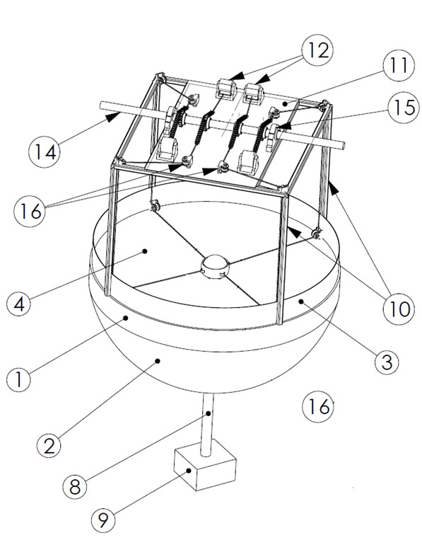
Figure 02

Figure 03
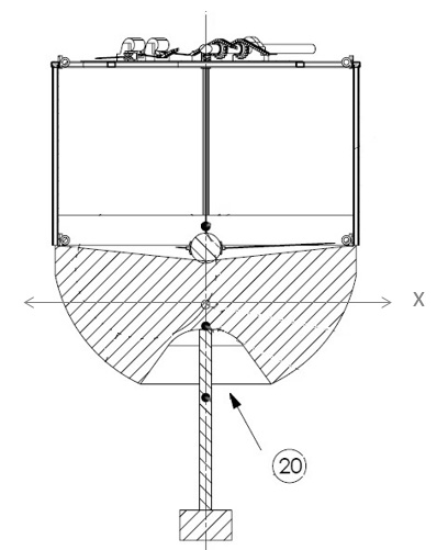
Figure 04
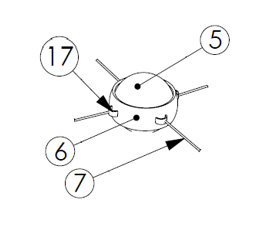
Figure 05
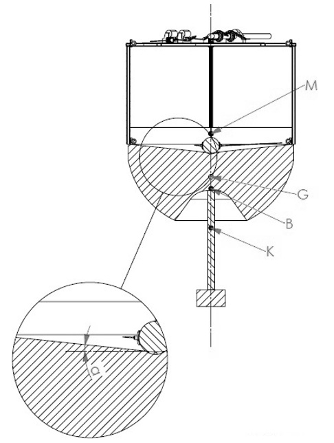
Figure 06
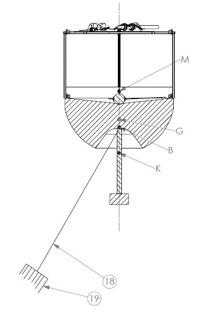
Figure 07
