A SHOE OR ADDITIONAL SOLE PROVIDED WITH MOTION MECHANISM AND MOTION TRANSMISSION UNITS
The invention concerns a shoe or additional sole comprising an external detachable and attachable drive member and the motion transmission units, wherein said shoe or additional sole enables the user to perform, whenever desired, the motorized motion under varying ground conditions owing to the motion mechanism it contains and wherein said shoe or additional sole is also suitable for use only as a shoe whenever desired by the user.
Description of the Figures
Figure 1. A sectional view of the one shoe of a pair connected to the drive member
Figure 2. A sectional view of the one shoe of a pair not connected to the drive member
Figure 3. A perspective view of the power unit and the motion transmission connection member
Figure 4. A side view of the shoe with the motion transmission connection member mounted
Figure 5. A detailed view of the motion transmission connection member and the driveline quick coupling apparatus
Figure 6. A bottom sectional view of the one shoe of a pair connected to the drive member
Figure 7. A side sectional view of a shoe pair comprising additional sole
Figure 8. A perspective view of the wheel form
Figure 9. A perspective view of the wheel form
Description of the Reference Numerals in the Figures
- Shoe body
- Sole
- Wheel shaft
- Wheel connection member
- Power unit
- Driveline
- Control unit
- Driveline quick coupling apparatus
- Drive shaft quick coupling connection
- Drive shaft
- Wheel shaft gear
- Drive shaft gear
- Additional sole
- Wheel
- Wheel shaft connection
- Wheel platform
- Heel
Description of the Invention
The invention concerns a shoe structure capable of motorized motion, wherein said shoe structure comprises only the simple transmission members with small volume and weight such as gear and shaft within the shoe, thereby avoiding any change in the volume and weight of the shoe, and wherein said shoe structure may be externally connected, in a detachable and attachable manner, to a power unit (5), embodying a power supply and a drive member, via an external driveline (6) with flexible and collapsible structure.
In this case, the shoe will not contain any component with relatively great weight and volume, such as the motor (drive member) or the battery (power supply). Since the shoe is formed using the simple components, it becomes possible to use the mechanism according to the invention with the known casual shoe forms without the need for developing special shoe designs in order to form the embodiment of the invention.
On the other hand, the teaching of the invention is not limited to the disposition of the simple transmission members such as gear and shaft in the shoe. It is possible to form the shoe with the capability of motorized motion by way disposing the simple mechanisms such as the gear and shaft in the shoe during the manufacture, while it is also possible to form the same by way of detaching the sole (2) connected to an existing shoe body (1) and attaching another sole (2), which embodies the transmission members like gear and shaft, to the shoe.
In this way, the new shoes to be manufactured will be provided with the motorized feature by positioning small parts into the same and the shoes currently in use will be able to be provided with a form in line with the object of the invention by simply replacing the soles (2) thereof.
After the shoe is equipped with the units appropriate for the motorized motion, the shoe is associated with the drive motor and the battery external to said shoe. In order to provide this association, it will be sufficient to simply transmit the generated motion to the shoe. A driveline (6) attachable to and detachable from the shoe is employed in order to provide said motion transmission. The driveline (6) has a flexible and collapsible structure so that the user can readily collapse and carry the same. During the use, the user unfolds the driveline (6) and connects the same between the shoe and the power unit (5).
The term power unit (5) as defined in the present invention refers to a pack or bag containing the drive member and the power supply. The drive member and the power supply may be present together within the power unit (5), while it is also possible to position the same separately from each other so that they will constitute the power unit and will be external to the shoe.
According to many embodiments of the invention, the drive member defines a motor, while the power supply defines a battery. In the different embodiments of the invention, the motor may be an electric motor. Owing to the approach of taking the drive member outside the shoe, the motor weight is no longer a problem; hence the embodiments incorporating a diesel motor are also encompassed by the invention.
Figures 1 and 2 illustrate the shoe pairs according to an embodiment of the invention. Since it is sufficient to transmit the motion to only one shoe of a pair in order to obtain the motion, it will be possible to connect the driveline (6) to only one shoe of the pair as illustrated in Figure 1. The embodiments involving the possibility of connecting the driveline (6) to both shoes in the pair are also covered by the scope of the invention.
In Figure 1, four wheel shafts (3) are positioned on the sole (2) in order to mount four wheels (14). At least one of the wheel shafts (3) disposed on the heel portion of the sole (2) is provided with a wheel shaft gear (11). The wheel shaft gear (11) is a member operating in a manner associated with the drive shaft gear (12). The motion generated on the drive shaft (10) is transmitted to the wheel shaft gear (11) via the drive shaft gear (12).
Referring to Figure 5, the drive shaft (10) is positioned into the drive shaft quick coupling connection (9). The drive shaft quick coupling connection (9) is an assembly member with structure suitable for connection with the driveline quick coupling apparatus (8) on the driveline (6). In this way, the driveline (6) may be connected to the shoe via the driveline quick coupling apparatus (8).
The wheel shafts (3), wheel shaft gear (11), drive shaft gear (12), drive shaft quick coupling connection (9) and drive shaft (10) described above are the parts positioned in the sole. The driveline (6), which bears the driveline quick coupling apparatus (8), is a part that may be externally connected to the shoe when required to be used.
Referring to Figure 6, the drive shaft gear (12) and the wheel shaft gear (11) are two gears that contact each other in a way to transmit motion to each other. The drive member, which is positioned in the power unit (5) and which obtains power from the power supply, transmits the motion to the driveline (6), which in turn transmits the motion to the drive shaft (10) positioned in the shoe. The drive shaft (10), when associated with the drive shaft gear (12), actuates the drive shaft gear (12). The drive shaft gear (12) actuates the wheel shaft gear (11) and thus the wheel (14) connected to said gear and thus the motion may be obtained on the shoe.
In Figure 7, the additional sole (13), which is an embodiment of the invention, is shown as applied on the existing shoes. The additional shoe (13) is a part, which may be mounted on the shoe as a detachable and attachable part or as a permanent part. The additional sole contains all of the wheel shafts (3), wheel shaft gear (11), drive shaft gear (12), drive shaft quick coupling connection (9) and drive shaft (10), which are the motorized motion transmission members positioned in the shoe, on at least one shoe of a pair.
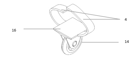
In the motorized shoe embodiment according to the invention, it is possible to employ the detachable and attachable wheels (14) on the wheel shafts (13). The detachable and attachable nature of the wheels (14) brings any kind of shoes into an extra motorized condition without altering the daily use function thereof. Further, the detachable and attachable nature of the wheels (14) provides the possibility to use different embodiments of the wheels (14) for various weather and road conditions. In this way, the shoes for daily use are provided with the multifunctional feature suitable for the ground and the conditions.
Figures 8 and 9 show the wheel embodiments able to be used for different embodiments of the invention. Referring to Figure 8, the wheel (14) is equipped with a wheel shaft connection (15). The wheel shaft connection (15) is connected with the wheel shaft (3) to connect the wheel (14) to the sole (2).
Figure 9 illustrates an embodiment concerning the wheels (14) to which no motion transmission is to be performed. The illustrated embodiment consists of the wheel connection member (4) providing the connection to the shoe and the wheel platform (16) constituting the basis for the placement of the shoe.
In Figure 3, those units of the motion mechanism positioned external to the shoe are shown. The power unit (5) is associated with the driveline (6) in a way to provide the motion transmission via the drive member. In order for the drive member included in the power unit (5) to be able to be controlled by the user, a control unit (7) is positioned into the structure.
According to the invention, the power unit (5) is disposed external to the shoe. In order to achieve this purpose, the power unit may be carried by the user via portable members such as a handbag or backpack or it may be carried via a separate system with wheels.
According to an embodiment of the invention, all of the wheel shafts (3), wheel shaft gear (11), drive shaft gear (12), drive shaft quick coupling connection (9) and drive shaft (10), which provide the shoe with motion, are positioned in the heel (17) of at least one of the shoes constituting the pair. In this case, these components to be positioned in the heel (17) may be positioned in the heel during the manufacture of the shoe, while the same goal may be achieved by way of replacement of a manufactured heel (17) with a heel (17) containing all said components.
Similar to the other embodiments of the invention, a driveline (6) is associated with the heel (17). The motion received from the power unit (5) by means of the driveline (6) is transmitted to the wheels (14) via the transmission members available in the heel (17). The power unit (5) is a member, which is positioned external to the shoe and which includes the power supply and the drive member.
CLAIMS
- A motorized motion mechanism embodying the wheels (14), operated in connection with the drive member in order to provide the casual shoe of a user with motorized motion when desired, characterized in that it is comprised by
- a driveline (6) with detachable and attachable structure, connecting the power unit (5) to the shoe in a way to provide only the motion transmission,
- a sole (2) or additional sole (13) without the drive member and the power supply, containing the transmission members and wheels (14) that enable the motion received from the driveline (6) to be transmitted to the wheels (14),
- a power unit (5) positioned external to the shoe, embodying the power supply and the drive member.
- Motorized motion mechanism according to Claim 1 characterized in that it comprises a power unit (5), which includes the power supply and the drive member positioned at different locations in a way to constitute said power unit (5) and to be disposed external to the shoe.
- Motorized motion mechanism according to Claim 1 characterized in that it comprises a power unit (5), which includes the power supply and the drive member positioned at the same location in a way to constitute said power unit (5) and to be disposed external to the shoe.
- Motorized motion mechanism according to Claim 1 characterized in that the wheel shaft/s (3) positioned in the sole (2) of at least one of the shoes constituting a pair is/are provided with a wheel shaft gear (11) able to receive the motion from the driveline (6).
- Motorized motion mechanism according to Claim 4 characterized in that it comprises the wheel shaft gear (11) associated with the drive shaft gear (12), which operates in connection with the drive shaft (10) receiving motion from the driveline (6).
- Motorized motion mechanism according to Claim 5 characterized in that it comprises the drive shaft (10) positioned into the drive shaft quick coupling connection (9), which is an assembly member with structure suitable for connection with the driveline quick coupling apparatus (8) on the driveline (6) to enable the connection of said drive shaft (10) with said driveline (6).
- Motorized motion mechanism according to Claim 4 characterized in that it comprises the drive shaft gear (12) and the wheel shaft gear (11), which are two gears contacting each other in a way to transmit motion to each other.
- Motorized motion mechanism according to Claim 1 characterized in that it comprises an additional sole (13), which is a component mounted to the shoe as a detachable and attachable part or as a permanent part.
- Motorized motion mechanism according to Claim 1 characterized in that it comprises the wheels (14) mounted to the wheel shafts (3) in a detachable and attachable or permanent manner.
- Motorized motion mechanism according to Claim 1 characterized in that it comprises the wheels (14) equipped with a wheel shaft connection (15).
- Motorized motion mechanism according to Claim 1 characterized in that it comprises the wheels (14) formed by the wheel connection member (4) enabling the connection with the shoe and by the wheel platform (16) constituting the basis for the placement of the shoe.
- Motorized motion mechanism according to Claim 1 characterized in that it comprises a power unit (5) associated with the driveline (6) in a way to provide the motion transmission via the drive member.
- Motorized motion mechanism according to Claim 1 characterized in that it comprises a control unit (7) enabling the drive member, disposed within the power unit (5), to be able to be controlled by the user.
- Motorized motion mechanism embodying the wheels (14), able to be operated in connection with the drive member in order to provide the casual shoe of a user with motorized motion when desired, characterized in that it is comprised by
- a driveline (6) with detachable and attachable structure, connecting the power unit (5) to the shoe in a way to provide only the motion transmission,
- a sole (2) or additional sole (13) with a heel (17) embodying all of the wheel shafts (3), wheel shaft gear (11), drive shaft gear (12), drive shaft quick coupling connection (9) and drive shaft (10),
- a power unit (5) positioned external to the shoe, embodying the power supply and the drive member.
- Motorized motion mechanism embodying the wheels (14), able to be operated in connection with the drive member in order to provide the casual shoe of a user with motorized motion when desired, characterized in that it is comprised by
- a driveline (6) with detachable and attachable structure, connecting the power unit (5) to the shoe in a way to provide only the motion transmission,
- a shoe embodying all of the wheel shafts (3), wheel shaft gear (11), drive shaft gear (12), drive shaft quick coupling connection (9) and drive shaft (10),
- a power unit (5) positioned external to the shoe, embodying the power supply and the drive member.
ABSTRACT
A SHOE OR ADDITIONAL SOLE PROVIDED WITH MOTION MECHANISM AND MOTION TRANSMISSION UNITS
The invention concerns a shoe or additional sole (13) comprising an external detachable and attachable drive member and the motion transmission units, wherein said shoe or additional sole enables the user to perform, whenever desired, the motion owing to the motion mechanism it contains and wherein said shoe or additional sole is also suitable for use only as a shoe whenever desired by the user. Said shoe or additional sole (13) comprises only the simple mechanisms with small volume and weight, such as the gear and shaft, within the shoe or the additional sole (13).
Figure 01
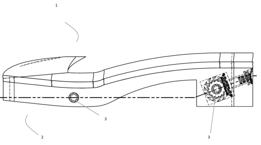
Figure 02
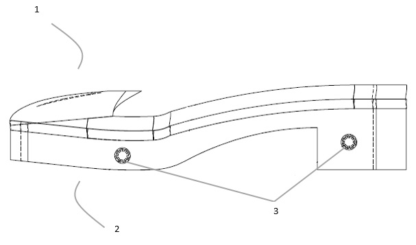
Figure 03
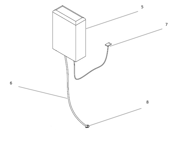
Figure 04
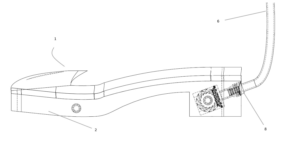
Figure 05
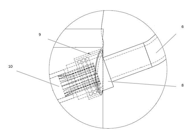
Figure 06
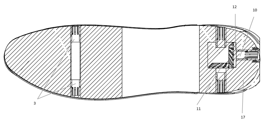
Figure 07
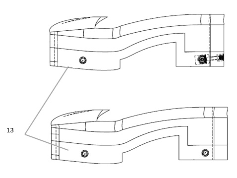
Figure 08
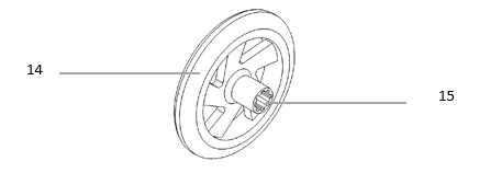
Figure 09
