The present invention relates to motion system for a wind turbine which transforms the kinetic energy of wind primarily into mechanical energy and then into electrical energy.
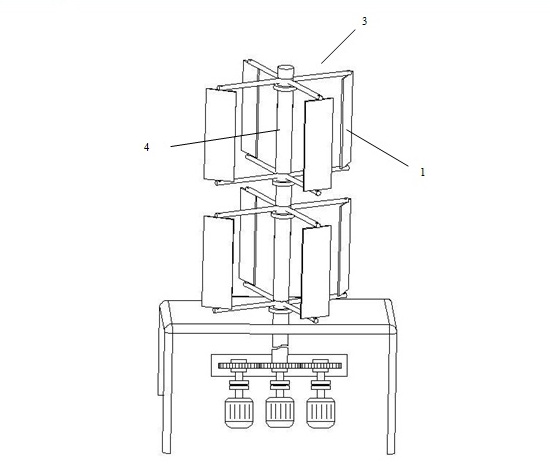
Brief Description of FiguresFigure 1 is a close view of various wing structures of wind turbine motion system.
Figure 2 is a detailed view (starting point) showing the case of crashing direction of wind to wing surface with 900 angle (making 00 angle with z axis) in regard to wind turbine motion system.
Figure 3 is a top view showing wing positions for the case of crashing of wind to wing surface with different angles in regard to wind turbine motion system.
Figure 4 is a detailed view of one wing showing the changing of wind-meeting angle of wing while the motion system is rotating, in regard to wind turbine motion system.
Figure 5 is the display of angles of said forces and the forces that affects on one wing in regard to wind turbine motion system.
Figure 6 is the display of various wing stabilisation positions of wind turbine motion system.
Figure 7 is the display of the section scanned by wings during the rotation of wind turbine motion system.
Figure 8 is a side view of wind turbine motion system as a whole.
Figure 9 is a detailed view showing the system adapted for naval platforms in regard to wind turbine motion system.
Figure 10 is a view of design structure aimed to gradually control power generation of motion system within wind turbine motion system.
Description of Components
1. Wing
2. Bedding point
3. Wing torque rod
4. Wing Actuating shaft
5. Wing slots
S. Surface area of the wing in air current
θ. Impact angle of wind to wing according to z axis
α. Rotation angle between wing torque rod and starting point
β. The angle that the wing has made to the x axis plane with its wing torque rod
F. Force affecting the wing surface in the direction of z axis
F’. Component vertical to wing plane in regard to the force affecting the wing surface in the direction of z axis
Fd. Component made a right angle to wing torque rod of component F’ which is the component of the force affecting the wing surface in the direction of z axis
V. Velocity of wind
In the structure of the present invention for wing turbine motion system, the working efficiency of system is increased by wind contact surface since there is a multi-blade (1) motion system having independent wings (1) instead of rotor system in order to get motion from wind.
Each of wings (1) can be arranged according to the direction of wind since the wings (1) since the wings (1) within wind turbine motion system of the present invention can make free rotation around bedding point (2). Therefore maximum benefit and energy can be obtained from the motion of the wind.
In order to arrange the structure of the present invention according to the direction of wind, it is sufficient to arrange the wings (1) merely. Thus, there is no need for electric motors the setting and operating costs of which is high in order to arrange said system according to the direction of wind.
When describing the wind turbine motion system of the present invention within description and claims part, x, y, z coordinate system is taken as reference. Y axis is extending along long edge of wing in this direction.
The term starting point described within description and claims of the present invention for wind turbine motion system indicates the impact of wind direction to wing plane with 90°C angle (0° angle with z axis) in other words indicatesthe initial state of the present invention for wind turbine motion system.
The present invention for wing turbine motion system comprises at least one actuating shaft (4) positioned vertically, at least two wing torque rod (3) positioned on said actuating shaft (4) for each wing (1) in proportion to wing number (1) and wings (1) connected to each wing torque rod (3) by means of at least one bedding point (2).Wings (1) can move freely in such a way that center point of motion will be the bedding point (2) since the above-mentioned wings (1) are fixed to the wing torque rods (3) from at least one bedding point (2).
Wings (1) can move freely in such a way that center point of motion will be the bedding point (2) since the above-mentioned wings (1) are fixed to the wing torque rods (3) from at least one bedding point (2).
Preferably, wings (1) are chosen as of rectangular shape. Wing slots (5) are positioned on each wing (1) for increasing the effect of wind on wings (1). The air particles collide with wing (1) vertically according to x, y axis when the wind crashes to wing (1) with 0° impact angle (θ) according to z axis and in this case all kinetic energy of kinetic air particles is taken by the wing (1). However, a part of kinetic air particles affecting the wing (1) surface flows over wing (1) when the impact angle (θ) of wind to wing according to z axis is a different value from 0°. Wing slots (5) prevents air going through the wing (1) easily and it provides impact effect of kinetic air particles, in other words driving power of wind, to affect more on wings (1). In addition to that, it benefits from friction effect of air particles in consequence of its productive effect. In the direction of said friction effect and power accordingly, the structures of wing slots (5) in other words the structures of small resistance surfaces positioned on wing (1) can be arranged and they can be formed in any direction and shape.
Within the present invention, the following equivalents are used in order to determine the effect of wind on wings (1). In which:
q = Kinetic energy of windρ = Specific weight of air
V = Velocity of wind
T = Torque force
F = Force affected on wing surface in the direction of z axis
R = Length of wing torque rod
S = Surface area of wing in air current
q = 1/2 ρ V²
By means of above-mentioned equivalent, kinetic energy of wind is provided. For wing (1) exposed to wind motion, when impact angle (θ) of wind to wing according to z axis is 0° and when the force (F) affected on wing surface in the direction of z axis is calculated, the following equivalent comes out. When said equivalent is analyzed, it will be seen that the magnitude of force (F) affected on wing surface in the direction of z axis depends on wing area and velocity (V) of wind.
F = q.SThe force (F) affected on wing surface in the direction of z axis and generated on wing surface area in air current generates torque on wing actuating shaft (4) by menas of wing torque rod (3) connected to wings (1). The equivalents with respect to generated torque force are presented in the following:
T = F.RT = q.S.R
Above-mentioned equivalents is valid for the case that the impact angle (θ) of wind to wing according to z axis is 0°. At first, since the wings (1) are stable in connection with system the impact angle (θ) of wind to wing according to z axis will be 0° but wings (1) start to move by means of wing actuating shaft (4) within system with the effect of first air particles crashing to the wing (1). Thereby, the receiving angle of wing (1) surface area relating to wind in air current is changed by rotating of system and consequently vertical component (F’) of the force (F) affected on wing surface in the direction of z axis and generated on wing (1) surface area in air current changes as well. Vertical component of the force (F) affected on wing surface in the direction of z, which provides the rotation motion of wing actuating shaft (4) and accordingly energy generation is (F’) within system. The equivalent regarding the vertical component of the force (F) affected on wing surface in the direction of z is given following:
F´ = F.Cos θ yani F´ = q.S.Cos θAs mentioned above, the force provided for necessary motion in order to allow system to produce energy is torque force and said torque force is under the effect of vertical component (F’) of the force (F) affected on wing surface in the direction of z. Also, the motion of wing actuating shaft (4) is provided by component (Fd) which makes a right angle to wing torque rod of the component (F’) of the force (F) affected on wing surface in the direction of z and affected on wing torque rod (3) basically. In this case, force equivalent of system will be as in the following:
Fd = F´.CosβIn this case, the equivalent of torque force is as the following:
T = R.q.S.Cosθ.Cosβ
When above-mentioned equivalents are examined, R mentioned in said equivalents in other words the length of wing torque rod (3) depends on wing surface area in air current (S), velocity of wind (V), impact angle of wing to wind according to z axis (θ) and the angle (β) that the wing (1) made according to x axis with its wing torque rod in order to obtain maximum efficiency from system. When system is setting, the length of wing torque rod (3) and wing surface area in air current can be determined according to user’s preference and velocity of wind (V) changes according to setting conditions and term of using the system. In order to increase energy efficiency of system, the value of Cos θ.Cos β which is the only arrangeable variable by user according to above-mentioned equivalents should be provided as having the maximum value. In order to keep the multiplication value of Cos θ.Cos β as high as possible, controlling of instant wing (1) positions continuously in other words the impact angle (θ) of wind to wing according to z axis and the angle (β) made by wing torque rod according to x axis should be arranged in such a way that maximum efficiency can be obtained.
Within our invention, various efforts has been made in order to maximize efficiency and hence Cos θ.Cos β value and consequently it is observed that maximum value is provided in case of θ = α/2 and
β = α/2.
With the wind crashing the wings (1), wings (1) start to rotate on wing actuating shaft (4) and hence rotation angle (α) made with starting point and wing torque rod changes by taking the starting point as reference according to instant position of each wing (1). Together with rotating wings (1) continuously, rotation angle (α) that the wing torque rod makes with starting point and changing wing torque rod should be measured by an apparatus and it should be arranged in such a way that multiplication of Cos θ.Cos β can take maximum value and wing (1) positions can take θ = α/2 and β = α/2 values in order to get maximum efficiency.
Wings (1) are inclined by using an eletronic inclining apparatus in order to make the impact angle (θ) of wind to wing (1) positions according to z axis and the angle (β) made with wing torque rod according to x axis to be suitable value of α/2. The impact angle (θ) of wind to wing (1) according to z axis and the angle (β) made with wing torque rod according to x axis plane are arranged continuously by measuring rotation angle (α) made with starting point of the wing torque rod by means of an electronical inclination system and by changing wing (1) positions. Together with motion of the system, the rotation angle (α) made with starting point and wing torque rod changes when position of each wing (1) has changed and electronic inclination apparatus arranges the impact angle (θ) of wind to wing (1) according to z axis and the angle (β) made with wing torque rod according to x axis continuously as α/2 according to these changing values.
Because of above-mentioned wing positions, electronic inclination system to be used within said system can be consisted of inclining units each of which is connected to each wing (1) seperately and also it can be used as a collective inclining unit for all wings (1) in order to arrange the impact angle (θ) of wind to wing (1) according to z axis and the angle (β) made with wing torque rod according to x axis.
The present invention for wind turbine motion system can transform mechanical energy obtained from wind power into electrical energy by means of an alternator just like in its similar kinds used in state of art. Similarly, the mechanical energy taken from wind turbine motion system can be used in stead of sail with a gear and different apparatus connected to wing actuating shaft (4) in order to provide motion in sailing ships instead of obtaining electrical energy. In this case, wind turbine motion system transfers the mechanical energy from wind directly to motion rotors and moves the vessel without need for sail or similar motion equipments.
By using the present invention for wind turbine motion system, a wind turbine motion system and also more than one coupled wind turbine motion system can be used in order to produce energy. Again, there are more than one alternator or mechanical system can be controlled by a control unit gradually and actively within the present invention for wind turbine motion system just like in wind turbines available in state of art. The control unit can control rotation speed and motions of system depending upon wind velocity and hence wind energy. Depending upon the information taken from these controls, it prevents energy loss by getting and removing of additive alternator or mechanical systems into circuit gradually and provides the designed system to work in much more unsteady weather conditions at very dominant productivity levels. Said control unit system prevents system to be damaged at high wind speed by braking or controlling the in such a way that wings (1) make a minor angle with wind and obtain less power.
The main object of the present invention for wind turbine motion system is to use such a control system which provides to generate minimum surface area by rotating wings to same direction with wind or stops the system definitely for protecting said system in maintenance periods and undesirable storm conditions as described above although it is setted in order to obtain maximum efficiency from wind energy.
This control system to be used includes different sensors of state of art and can control the information taken from these sensors, the system and the wing (1) angles by means of mechanical systems according to PC-PLC-containing analysis and the program installed depending upon this analysis. By means of contol system including system or wing (1) gear system, servomotors with chain system, hydrolic system and pneumatic system, one of many alternatives of state of art can be adapted to said designed system.
The present invention for wind turbine motion system can be used as vertical-axial while it can be used as horizontal-axial in some models. In vertical-axial usages, wing actuating shaft (4) is positioned vertically in the system. In horizontal-axial usages, wing actuating shaft (4) is positioned horizontally in the system.
TO RENEW CLAIMS
1. A wind turbine drive system which has at least one vertically positioned blade drive shaft (4), and at least two blade support arms (3) on said blade drive shaft (4) for each blade (1) in proportion to the number of blades (1), and which has blades (1), which are coupled to each blade support arm (3) by means of at least one bearing point (2) on said blade support arms (3), and which uses a guidance system so as to be able to move the blades in such a way that the bearing point (2) will be the central point of movement of said blades (1), characterized in that the wind’s angle of attack (θ) to the blade with the Z axis and the blade’s angle (β) made with the X axis plane by its own blade support arm are arranged at one half of the rotation angle (α) made with the start point of the permanent blade support arm, so that the blade (1) orientation, i.e. their angles, continually achieve optimal efficiency.
2. A wind turbine drive system as described in claim 1, characterized in that
• the rotation angle (α) of the blade support arm with the start point, as based upon each blade’s (1) position at each moment when the blade drive shaft (4) starts to rotate as the wind strikes the blades (1), is being measured by a device continuously.
• in accordance with the values received at each moment, the wind’s angle (θ) of attack to the blade with the Z axis and the blade’s angle (β) made with the X axis plane by its own blade support arm, are adjusted continually by means of an electronic blade (1) steering apparatus in order to acquire the value α/2.
3. An electronic steering apparatus as described in the claims above, characterized in that it measures the rotation angle (α) made with the start point by the blade support arm, which is measured for each blade (1) at each moment and which can be different for each blade, and that it is able to adjust the angle(θ) of attack of each blade (1) to the Z axis and the blade’s angle (β) made with the X axis plane by its own blade support arm, so as to acquire the value α/2 for each blade (1) separately.
OLD CLAIMS
1. The motion system for wind turbine; characterised in comprising at least one actuating shaft (4) preferably positioned vertically, at least two wing torque rod (3) positioned on said actuating shaft (4) for each wing (1) in proportion to wing number (1) and wings (1) connected to each wing torque rod (3) by means of at least one bedding point (2).
2. The wings of the present according to Claim 1; characterised in that they can move freely in such a way that center point of wing (1) motion is bedding point (2).
3. The wings of the present invention according to Claim 1; characterised in that wing (1) surface consists of a smooth surface and there are wing slots (5) which generate small resistance surfaces on it.
4. The wing actuating shaft (4) of the present invention according to Claim 1; characterised in that it can be positioned vertically for vertical-axial systems and it can be positioned as horizontally for horizontal-axial systems.
5. The wind turbine motion system compatible with above-mentioned claims; characterised in comprising an electronic inclination system which controls the positions of all wings (1) by bringing the impact angle (θ) of wind to wing according to z axis and the angle (β) made with wing torque rod according to x axis to α/2 value when wings (1) are in motion.
6. The wind turbine motion system compatible with above-mentioned claims; the working principle of which is characterised as following:
• Measuring of the rotation angle (α) of wing torque rod with starting point for changing wing positions by means of electronic inclination system continuously,
• According to measured values of the rotation angle (α) of wing torque rod with starting point, arranging as α/2 continuously by changing wind positions of the impact angle (θ) of wind to wing according to z axis and the angle (β) made with wing torque rod according to x axis plane,
• According to measured values of the rotation angle (α) of wing torque rod with starting point, controlling the impact angle (θ) of wind to wing according to z axis and the angle (β) made with wing torque rod according to x axis plane by means of electronic inclination system depending upon the wish to obtain different energy in such a way that they get different values from α/2 value.
7. An electronic inclination system according to above-mentioned claims; characterised in that the arrangement function of impact angle (θ) of wind to wing according to z axis and the angle (β) made with wing torque rod according to x axis plane can be performed by inclination units connected to each wing (1) seperately and on the other hand a collective inclining unit can be used for all wings (1).
8. The motion system for wind turbine; characterised in that it can generate motion for vessels by transferring mechanical energy taken from motion system to wing actuating shaft (4) by means of connected gear or different apparatus.
Figure 01

Figure 02
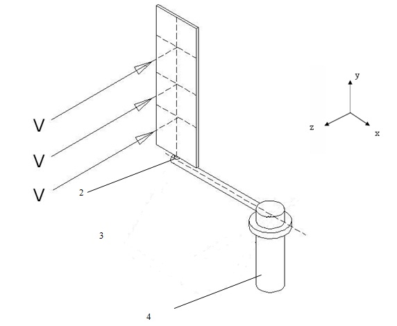
Figure 03
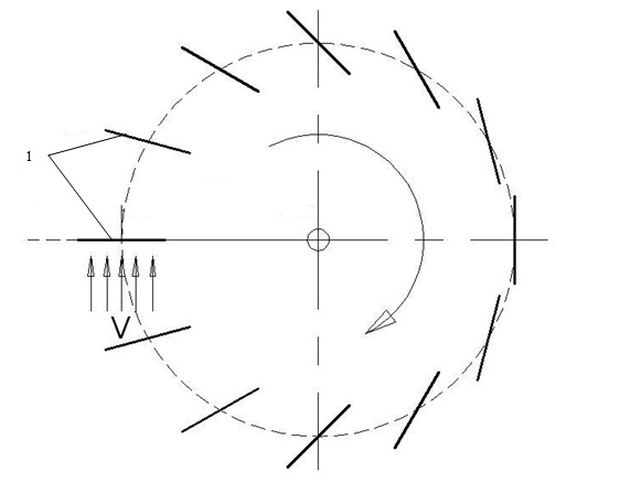
Figure 04
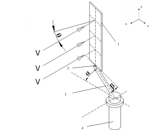
Figure 05
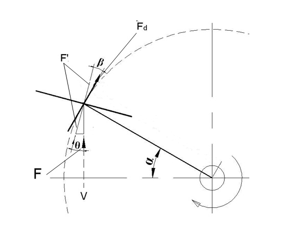
Figure 06
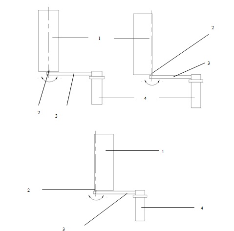
Figure 07
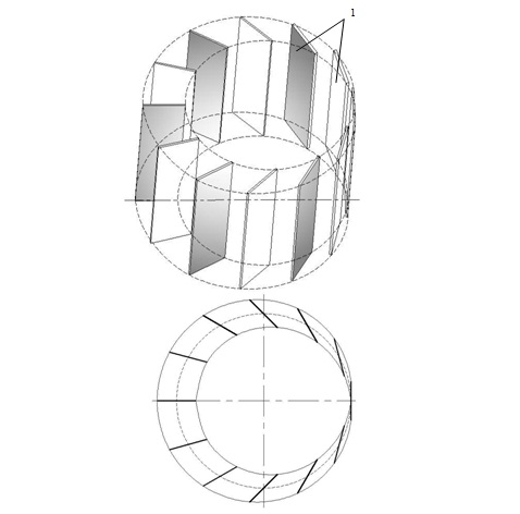
Figure 08
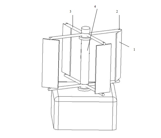
Figure 09
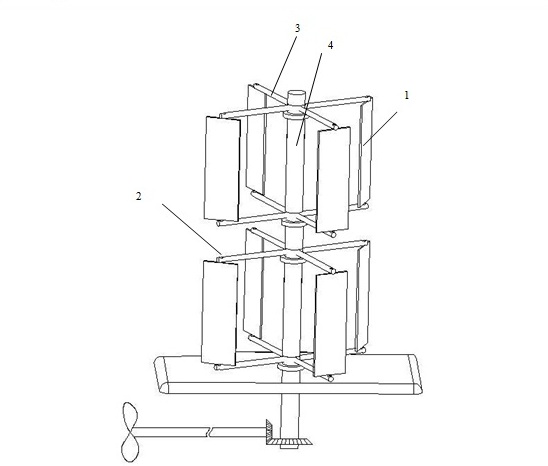
Figure 10
