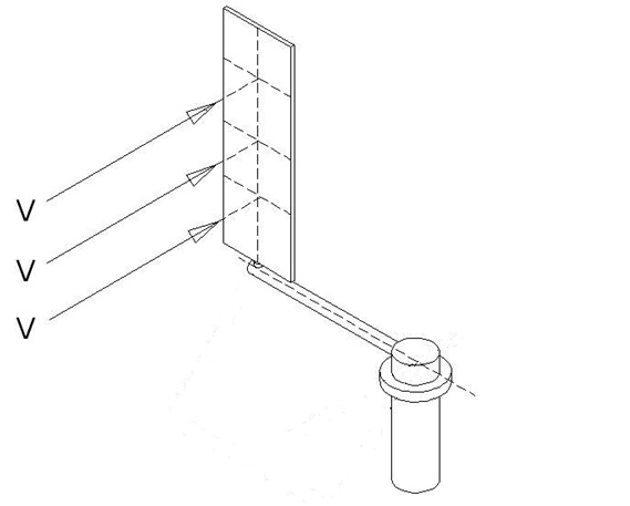
Descriptive animation display for my Project called “A WIND TURBINE MOVEMENT SYSTEM” for producing electricity from wind power which is a renewable energy resource is outlined above. Here a gear system has been used for controlling the wings since the diameter of the system is small. While the wings are connected to the main system by means of the gear system (governor gear), they automatically assume the position, where an optimum benefit will be obtained, depending on the blowing direction of the wind during the circular movement. In the case that the wind changes its direction, the position of the gear at the center, which is called as governor gear, is changed by means of a hydraulic engine and system and thus the wings are provided to assume an optimum position depending on the new blowing direction of the wind (since the wing drive gears are directed by this governor gear).
Many different control and drive systems available in the current technology can also be used instead of the wing control gears and directing governor gear which are used in the system of the said animation display. The main objective of the system is to absorb the wind energy with the help of resistance and friction methods by forming an effective and large surface area in the blowing direction of the wind by means of wings. The projected system is a wind turbine with a vertical axis and it can position the system and the wings in a way that they will generate a resistance against the wind at an optimum level with the help of the gear and hydraulic equipments used in the animation (or by using other controllimg systems) and to direct and control the wings for the positions from which optimum advantage will be obtained during the whole circular movement and at each movement stage.
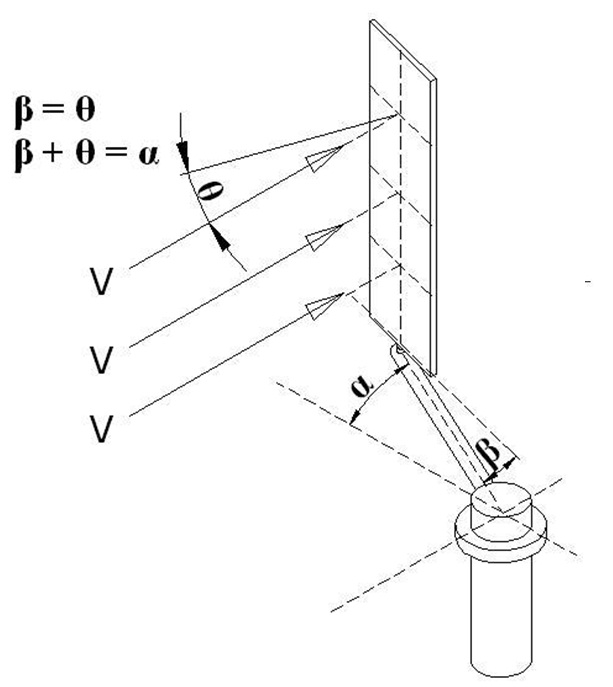
The wings at a starting position according to the blowing direction of the wind in Figure 1 make a vertical angle to the wind and generate an optimum resistance surface. Optimum resistance angles (β values) that the wing will make during the circular movement which starts with the movement of the system (Figure 2) have been analyzed under the title “ANGLE ANALYSIS”. As it can also be deduced from the values here, when the α = 0° is accepted as the initial state of the system and as the starting point for the wing to meet the wind with a right angle (Figure 1), as the system rotates the wing should be controlled in a way that it will make a β angle with its effort arm (with the help of gear, hydraulic, pneumatical systems, etc.) and the wing should be directed to β angle momentarily. While the β angles are being examined in “ANGLE ANALYSIS”, it has been taken into consideration that the force transmitted to the power shaft with the help of the effort arm to which the wing is connected, can only be provided with the force vector (Fd) effecting the effort arm with a right angle.
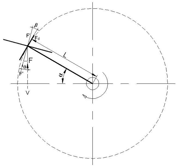
The vector arm expressed as Fd in Figure 3 is the force vector arm having a right impact on the L-radius effort arm of the F force to be obtained from the surface of the wing. Therefore the reasearch in the “ANGLE ANALYSIS” page is analyzed for the positions where the value of Fd = F x Cos²β is maximum.
It has been observed in the analysis carried out during the whole circular movement that maximum Fd value is provided at β = α/2 positions. Based on this data, total Fd force to be obtained from the system that we have planned in one complete revolution is
for one circular cycle which is 0---2π.Fd = F ∫ Cos² α/2 dα
Where F = ½ ρV² CH
F = is the force impacting on the wing at a right angle position
ρ = is the specific gravity of the air ( 1,25 kg/mᶟ )
H = is the height of the wing
C = is the width of the wing
Fd = is the F force vector arm impacting vertically on the level arm (L)
L = is the distance between the wing axis and shaft axis (level arm).
As a result of the integral calculation, Fd value is obtained for one cycle, and if we divide this obtained value with 2π, we obtain an instant Fd force that may be considered as stable in circular movement. Now it is sufficient to examine the speed factors for force calculation.
NOTE : Our studies both in electronical environment and in scaled drawing paper are presented below for your analysis. The result of the above
Fd = F ∫ Cos² α/2 dα imathematical expression is
Fd = ½ F (this result is obtained by dividing the value that we have obtained to find instant Fd force for one complete revolution with 2π).
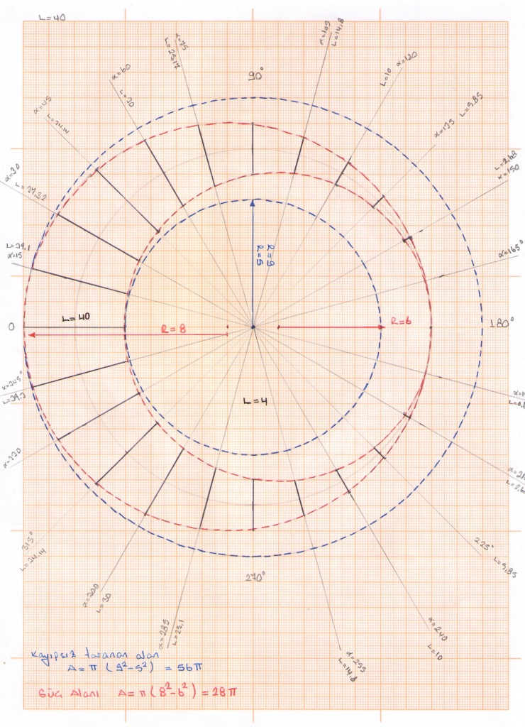
Our objective was to test the accuracy of the mathematical result expressed above. In both of the studies, calculations have been made for the different positions (C=40 mm) of the circular movement and they have been turned into graphics. As is seen in both of the studies, if the wing was made stable during the circular movement, the area to be swept would be doubled compared to the area to be swept in one complete revolution with the controlled wing movements dependion on our β =α/2 respect. The values obtained both from the mathematical and practical calculations are the same.
The blue area in the figure is formed by momentarily calculating the Fd force that is generated on the wing according to α angle at each level and which is impacted vertically on the force shaft based on the above mathematical respect. If the pink are in this figure is considered as the area that can be swept with the whole circular movement (where C=40 mm), here Fd = ½ F ratio is obtained.
In study carried our on this scaled drawing paper, it is seen that 56π value is two times 28π value, therefore we obtain the same result.
Figure 01

Figure 02

Figure 03

Figure 04

scaled drawing paper
