For the first position when the blowing direction of the wind makes a right angle to the wing as in Figure 1 ( ϴ = 0° )
F = ½ ρV²S
S = C x H
F = ½ ρV²CH
ρ = is the specific gravity of the air
S = is the surface area of the wing that we have determined
C = is the width of the wing
H = is the height of the wing
R = is the radius of the system
L = is the distance between the wing axis and the center axis of the shaft
When the system starts to move with the reaction of the wind, as shown in Figure 2, the wing will assume a β angle with the help of its level arm for the system that makes a α angle depending on the initial position. (We control the wing positions during the whole circular movement in such a way that β = α/2 value is obtained.)
When we analyze the force vectors generated for the position in Figure 2, we see the force vector arm, referred as Fd in Figure 3, that makes a right angle to the “L” level arm. This Fd force vector arm is the vectoral arm of the F force which tries to rotate the system in the most effective way, wherein the said vectoral arm makes a right angle to the level arm. The correlation between F and Fd is as follows.
Fd = F Cos²α/2The said correlation which is expressed as above is preserved during the whole circular movement and it corresponds to the area in the shape of a crescent present in our study that we have carried out with a scaled drawing paper as shown in Figure 4. It has been observed in this practical study that the area swept with the Fd = F Cos²α/2 correlation ( 28π ) corresponds to the half of the area ( 56 π ) swept with the circular movement when the wing angle is never changed, in other words F /2 = Fd equality is obtained.
When we wish to confirm this study, that we have practically carried out, with mathematical expressions:
F = ½ ρV²S
F’ = F Cosϴ
Fd = F’ Cosβ
ϴ = α/2
β = α/2
Fd = F Cosϴ Cosβ
Fd = F ( Cos α/2) ( Cos α/2 )
Fd = F Cos²α/2
0---2π that is the total Fd force for one cycle
Fd = F ∫ Cos²α/2 dα
Fd / F = ( (2π/2) + (Sin 2π/2) ) - ( (0/2) + ( Sin0/2 ) )
Fd = F π is obtained.
Since the obtained value is a circular cycle, the value of one instant Fd force vector arm that depends on the F force is obtained through division with 2π’ expression.
Instant Fd vector arm = Fπ / 2π Fd = F / 2 values are detected. The obtained value is matched with the micrometric paper and the drawing results on the computer.
FOR THE EXAMPLE FORCE CALCULATION
With the mechanism in Figure 5, the area that the system sweep in one cycle depending on Fd = F Cos²α/2 correlation will be same with the one in Figure 6:
We have previously determined from the Fd = F ∫ Cos²α/2 dα expression for the whole circular movement that Fd = πF and that one instant Fd force is F/2. If we make calculations for the parts in Figure 6 separately;
For the 1st part
for the part Fd1 = 0----π/2
Fd1 = F ∫ Cos²α/2 dα
Fd1 / F= π/4 + 1/2
For the 2nd part
for the part Fd2 = π/2----π
Fd2 = F ∫ Cos²α/2 dα
Fd2 / F = π/4 – 1/2
For the 3rd part
for the part Fd3 = π----3π/2
Fd3 = F ∫ Cos²α/2 dα
Fd3 / F = π/4 – 1/2
For the 4th part
for the part Fd4 = 3π/2----2π
Fd4 = F ∫ Cos²α/2 dα
Fd4 / F = π/4 + 1/2
π/4 + 1/2 = 1.285398
π/4 – 1/2 = 0.2854
If we replace the expressions in Fdt = Fd1 + Fd2 + Fd3 + Fd4 equation for one cycle Fdt = 3.1415 F equation is obtained.
If we divide both sides of the equation with 2π for the instant Fd forceFd = Fdt / 2 π
Fd = 3.1415 F / 2 π
Fd = F / 2
again we obtain the same result. Now let us try to find the instant speeds of the wings depending also on the number of cycles of the system during the circular movement:
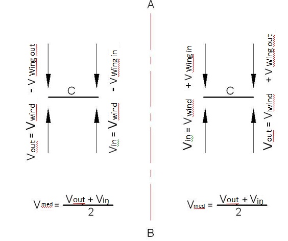
If we take Figure 7 into consideration, on the left side of the AB axis the wings rotates in the same direction with the wind and on the right side of the AB axis the wings rotates in the opposite direction of the wind. Again during the circular movement the linear velocity of the outer edge and the inner edge of the wing will be different. Due to the circular movement, the velocity at the outer edge of the wing is great but the velocity at the inner edge is less. The velocity at the wing surface positions that change depending on the distance between the wing surface and the center is in the same direction for the left part of the AB axis and the velocity values which are relative depending on the speed of the wind again will vary throughout the wing surface. Therefore the force to be generated on the surface will be different depending on the speed of the wind, the distance of one point on the wing to the center and also on the number of cycles.
Now if we analyze the circular movement of the wings in Figure 7 and their relative speeds dependant on the speed of wind in terms of the number of cycles in Figure 8, the relative speeds to be generated on the surface of C wing will correspond to one of the options (a-b-c) in Figure 8, where the speed of wind is signified with V.
For the conditions Figure 8-a / 8-b / 8-c, Area = A = 1/2 ( Vw.out + Vw.in ) C is obtained. And if Vmed expression is used for the speed of wind effecting momentarily on the surface of the wing,
Vmed = 1/2 ( Vw.out + Vw.in) is obtained. As a result of all these analysis,if P = 1/2ρV²S ( V1 – V2 ) , then P = 1/2ρV²S Vmed is obtained.
NUMERICAL EXAMPLE
| V = 4 m/s | Wind speed |
| N = 4 | Number of wings |
| C = 0.3 m | Wing width |
| H = 20 m | Wing height |
| 2R = 1 m | Full diameter of the system |
| 2L = 0.7 m | Distance between the wing axis |
| 2L+C/2 = 085 m | Width of frontage that the system meets the wind |
| Rpm = 50 min-1 | The number of the revolution of the system per minute |
In Figure 6, when the relative Vmed is calculated for the left part of AB axis,
the outer edge of the C wing cover 4xR = 2 m ground in one revolution.
Vw.out= (2 m/rev.) x (50 rpm) = (2 x 50)/60 = 100/60 = 1.666 m/s
Vw.out = 1.666 m/s
The inner edge of the C wing cover 4 x ( R –C ) = 4 x ( 0.5 – 0.3 ) = 0.8 m ground in one revolution.
Vw.in= ( 0.8 m/rev. ) x ( 50 rpm ) = 40 / 60 = 0.666 m/s
Vw.in = 0.666 m/s
Note : These obtained values are quite realistic values.
Vmed x 2 = ( 4 - 1.666) + ( 4 – 0.666 )
Vmed = 2.834 m/s
For the right side of AB axis
Vmed x 2 = ( 4 + 0.666) + ( 4 + 1.666 )
Vmed = 5.1666 m/s
Power for the left side of AB axis
P = ( Fd1 + Fd4 ) Vmed / 2π
P = 2F ( 1.285398 ) Vmed / 2π P = 1.285398 F Vmed / π
P = 0.409155 F Vmed
F = 1/2ρV²S S = N x C x H S = 4 x ( 0.3 ) x 20 = 24 m²
F = (1.25) x ( 4 )² x ( 24 ) /2 = 240 N
P = ( 0.409155 ) ( F ) ( Vmed ) = ( 0.409155 ) ( 240 ) ( 2.834 )
Pleft = 278.29 Nm/s
Power for the right side of AB axis
P = ( Fd2 + Fd3 ) Vmed / 2π
P = 2F ( 0.2854 ) Vmed / 2π = 0.09085 F Vmed
P = ( 0.09085 ) ( 240 ) ( 5.166 ) = 112.64 Nm/s
Pright = 112.64 Nm/s
The total power of the system
Ptot = Pleft + Pright
Ptot = 278.29 +112.64
Ptot = 390.93 Nm/s
When the potential power is calculated based of Figure 5
Ppotential = ½ (ρVᶟS )
Spot = H ( 2L + C/2 )
Spot = 20 ( 0.85 ) = 17 m²
Ppotential = ( 1.25 )( 4 )ᶟ ( 17 ) /2 = 680 Nm/s
Ppotential = 680 Nm/s
The capacity of our system = ( 390.93 ) / ( 680 ) = 0.5749
Capacity of the system ɳ = 0.5749
Different wind powers and the power and capacity calculations of the wind turbine with vertical axis stated in the table are calculated with the above-mentioned method and tabularized.
For system revolution 50 rpmV (m/s) |
2R (m) |
H (m) |
C (m) |
N |
Ptot (Nm/s) |
Ppot (Nm/s) |
Capacity ( ɳ ) |
4 |
1 |
20 |
0.3 |
4 |
390.93 |
680.00 |
0.5749 |
7 |
1 |
20 |
0.3 |
4 |
2299.73 |
3644.37 |
0.6310 |
8 |
1 |
20 |
0.3 |
4 |
3483.00 |
5440.00 |
0.6400 |
10 |
1 |
20 |
0.3 |
4 |
6943.36 |
10625.00 |
0.6535 |
12 |
1 |
20 |
0.3 |
4 |
12158.44 |
18360.00 |
0.6622 |
14 |
1 |
20 |
0.3 |
4 |
19489.00 |
29155.00 |
0.6685 |
16 |
1 |
20 |
0.3 |
4 |
29295.12 |
43520.00 |
0.6731 |
18 |
1 |
20 |
0.3 |
4 |
41936.60 |
61965.00 |
0.6767 |
20 |
1 |
20 |
0.3 |
4 |
57773.75 |
85000.00 |
0.6797 |
Figure 01
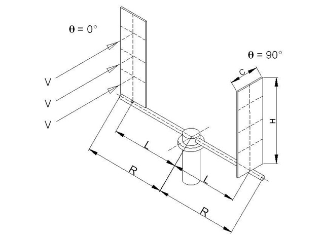
Figure 02
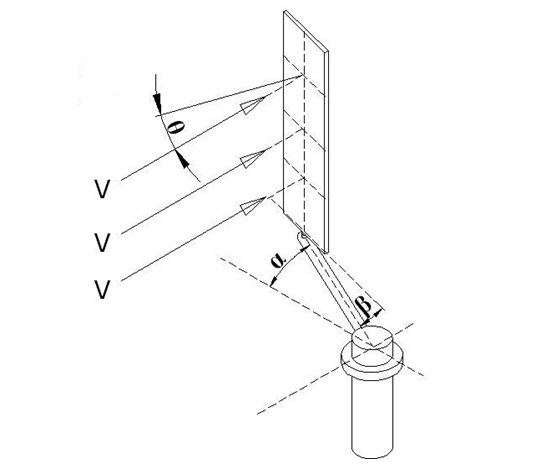
Figure 03
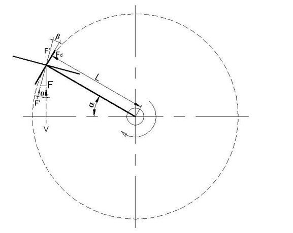
Figure 04
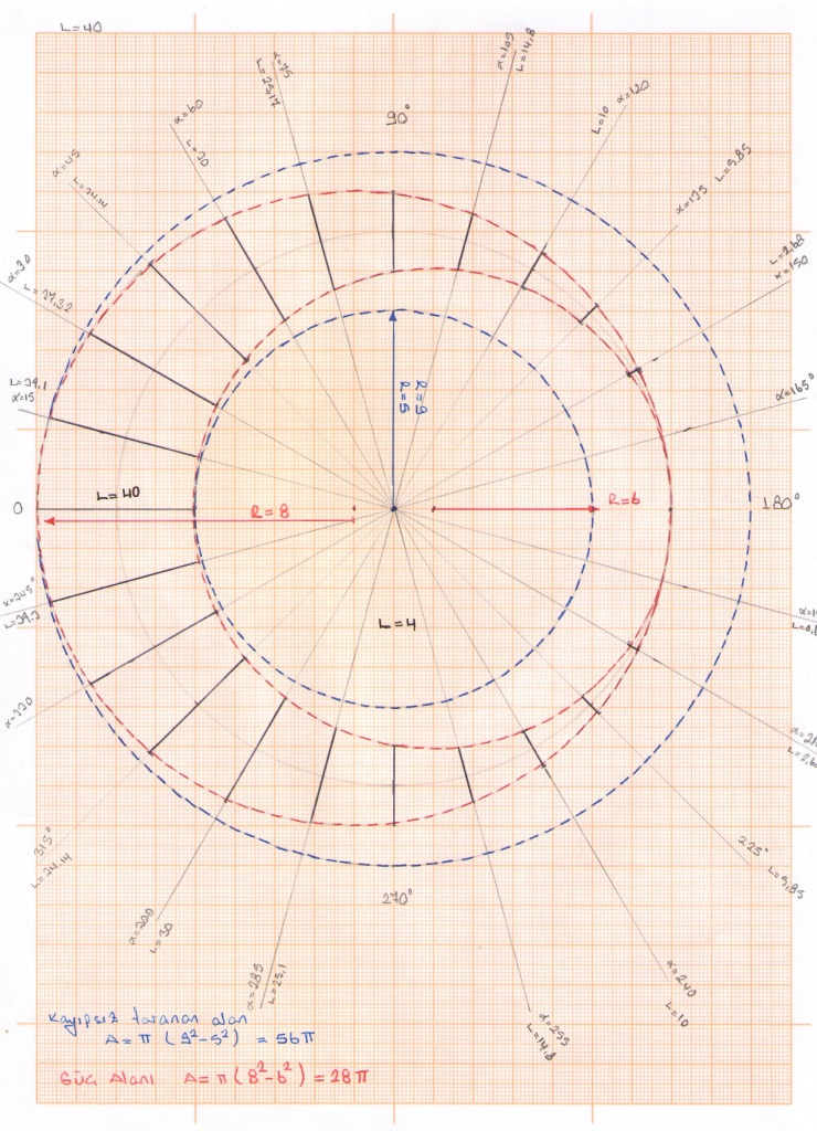
Figure 05
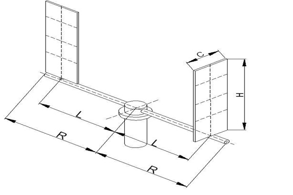
Figure 06
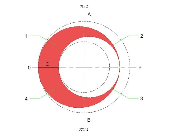
Figure 07
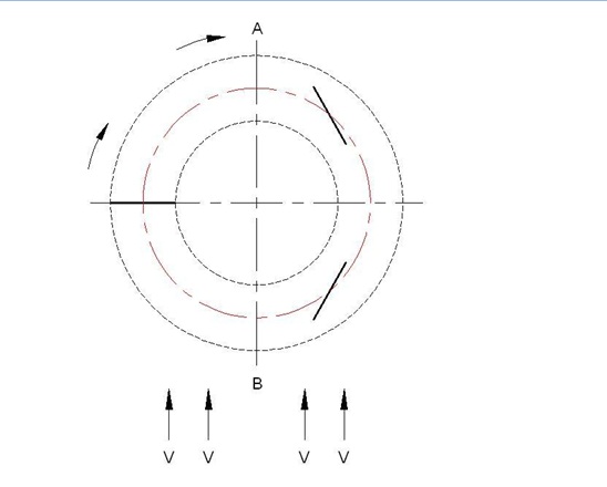
Figure 08
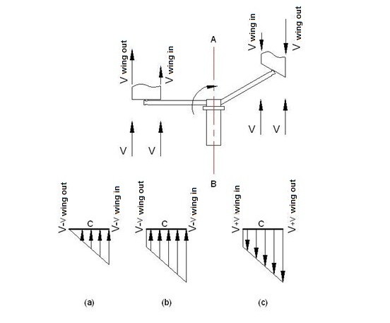
Figure 09
