NOW, MY NOVEL MANNER OF APPROACH
During my prototype studies in 2009-2010, the system was confirmed to be efficient. However, the fact that the wing continuously assumed different angles on the rotational axis as a matter of operating principle of cyclogyro/cyclocopter was noted to have a considerable adverse effect on the stability of the system. This is observed to a certain extent also in the studies by the company D-dallus as far as understood from the images on the internet environment. At this point, I have adopted a novel manner of approach, which I believe would enable us to resolve the stability issue more easily. According to this manner of approach, the wings are to perform the active, real work only during the half of the cyclic motion, while assuming an inactive/neutral state during the other half. In this manner, even though the efficiency of the system is partially reduced, it could still be quite efficient compared to the helicopters and besides, the mechanism of the system and the control system could be simpler and lighter and the vehicle could have the ability of flying much more easily and of being controlled much more easily;
Here are the details of my novel manner of approach:
ANIMATION SHOW
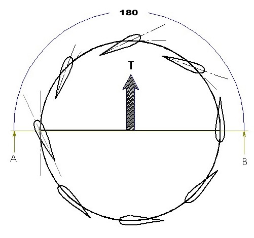
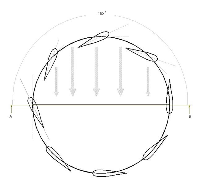
Referring to the animation, if we pay attention to the angles of incidence assumed by the wings with respect to the rotational axis during their cycle, we can see that the wings perform the real work only along the semicircle (through a 180-degree cyclic motion) and according to an angle of incidence we determine, whereas they perform no real work along the other semicircle since they move at the same angle as the cyclic axis. The position and angle of this semicircular orbit along which the wings perform active work by assuming an angle of incidence are in a state allowing us to control the same. The two-dimensional illustrations of the semicircular cycle along which the wings perform real work and generate the thrust/lift are shown in Figure : 1 and Figure : 2.

Figure : 1

Figure : 2
In Figure : 1, the positions at non-zero angles assumed by the wings during their cyclic motion along the upper semicircle (in a 180-degree cycle) of the section AB are shown and the direction of the lift corresponding to these positions of the wings is indicated.
In Figure : 2, the direction of the air flow is shown schematically again in a cyclic angular motion of the wings along the upper semicircle of the section AB. Here the wings perform real work and try to lift up the system while pushing the air downwards in the direction indicated by the arrows.
I believe that owing to this operating principle, the mechanism that controls the angles of the wings in the system would have a much simpler and hence lighter structure and that owing to the orientation of the wings only along the semicircle, the stability problem of the system could be overcome more easily. Thus, it rests with only a proper team, a proper collaboration and a little work to build a lighter and more stable personal air vehicle.