CONTROLLABLE MOTION SYSTEM ABLE TO BE USED FOR THE AIR VEHICLES
Our system concerns a motion mechanism with cycloidal rotor wherein the motion regime and thus the direction of motion may be controlled through the collective control over the wings contained by said mechanism. Said motion mechanism features a structure with the ability of being used for the guidance of the air vehicles.
Description of the Figures
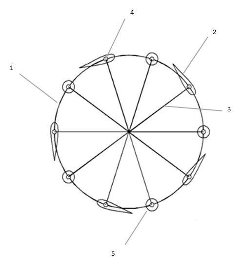
Figure 1. A representation of the motion mechanism circular section at the position at which the wings thereof assume an angle of incidence of 0°
Figure 2. A further representation of the wings on the motion axis
Figure 3. A representation of the wing structure
Figure 4. A representation of the motion mechanism circular section at the position where an angle of incidence is provided to the wings thereof in the 180°-part, while the wings thereof assume an angle of incidence of 0° in the other part
Figure 5. A representation of the motion mechanism circular section at the position where an angle of incidence is provided to the wings thereof in the 120°-part, while the wings thereof assume an angle of incidence of 0° in the other part
Figure 6. A view of the direction options for the force vectors able to be generated by the motion mechanism
Figure 7. A representation of the motion mechanism circular section and the direction of air flow at the position where an angle of incidence is provided to the wings thereof in the 180°-part, while the wings thereof assume an angle of incidence of 0° in the other part
Figure 8. A view of the motion mechanism circular section having the intermediate weights and wings.
Description of the Reference Numerals in the Figures
- 1. Motion mechanism circular section
1.1. Primary circular section arc
1.2. Secondary circular section arc
- 2. Wing
- 3. Connection member
- 4. Connection point
- 5. Intermediate weight
α. Angle of incidence
A. Arc segment A
B. Arc segment B
C. Arc segment C
D. Arc segment D
T. Force vector
H. Air flow direction
DESCRIPTION OF THE SYSTEM
The cycloidal motion mechanisms consist of a body with cylindrical form and the wings (2) positioned on the sides of the body. The wings (2) may be used to guide the air. In this way, the mass to which the motion mechanism is connected or the motion mechanism may be moved.
Each wing (2) constituting the motion mechanism is connected to a motion shaft via the connection member (3) at the connection point (4) of the wing. The motion shaft is usually positioned at the center of the body with cylindrical form.
The invention relates to the fixing of the angles of incidence (α) of the wings, present in an at least 180° arc segment of the motion mechanism circular section (1), to the value of 0° in order to enable the motion mechanism or the mass to which the motion mechanism is connected to move in the desired direction. The angles of incidence (α) of the wings (2) present in the remaining portion of the motion mechanism circular section (1) have in this state a value different from 0°. In this way, a force vector (T) may be generated in the direction of the secondary circular section arc (1.2), thereby enabling the motion mechanism or the mass to which the motion mechanism is connected to move in said direction.
The secondary circular section arc (1.2) defines the arc segment on the motion mechanism circular section (1) where the angles of incidence (α) of the wings thereof are different from 0°, whereas the primary circular section arc (1.1) defines the arc segment on the motion mechanism circular section (1) where the angles of incidence (α) of the wings thereof are 0°. The sum of the secondary circular section arc (1.2) and the primary circular section arc (1.1) constitutes the motion mechanism circular section (1).
In Figure 1, the motion mechanism circular section (1) is shown in the position at which all the wings (2) have an angle of incidence (α) of 0°. In this state, the primary circular section arc (1.1) is 360 °, while the secondary circular section arc (1.2) is 0°. In this case, the system will be at rest as it will not generate power.
In Figure 4, the primary circular section arc (1.1) is defined to be 180°; hence the secondary circular section arc (1.2) is also defined to be 180°. In this condition, a force vector (T) perpendicular to the direction of the secondary circular section arc (1.2) may act upon the system from the center of the motion mechanism circular section (1).
Similarly, in Figure 5, the primary circular section arc (1.1) is defined to be 240°; hence the secondary circular section arc (1.2) is defined to be 120°. In this condition, a force vector perpendicular to the direction of the secondary circular section arc (1.2) may act upon the system from the center of the motion mechanism circular section (1). However, the force of the force vector generated in this case is smaller than that for the force vector given in Figure 4.
It is possible to determine the direction of the force vector (T) acting upon the system by altering the position and length of the secondary circular section arc (1.2) on the motion mechanism circular section (1). In Figure 6, the directions for the force vectors (T) able to be generated for different positions of the secondary circular section arc (1.2) are shown.
The direction of the force vector (T) may be regulated by forming the secondary circular section arc (1.2) at different arc segment positions on the motion mechanism circular section (1).
For example, in case the secondary circular section arc (1.2) is comprised by the arc segment A (A) and the arc segment B (B), the force vector (T) is generated in the direction of y-axis.
In case the secondary circular section arc (1.2) is comprised by the arc segment B (B) and the arc segment D (D), the force vector (T) is generated in the direction of x-axis.
In case the secondary circular section arc (1.2) is comprised only by the arc segment C (C), the force vector (T) is generated in the direction of the exact middle axis of –x and –y.
In order to form the secondary circular section arc (1.2) and the primary circular section arc (1.1), one may employ the hydraulically, pneumatically, mechanically and electrically controlled systems. These systems are the mechanisms with a structure fixing the angles of incidence (α) to 0° for all the wings (2) within the primary circular section arc (1.1). Said mechanism is referred to as the fixing mechanism in the following sections of the specification.
It is also possible to position a mechanism on the secondary circular section arc (1.2) for setting the angles of incidence (α) to a value different from 0° for all or some of the wings (2).
In order to be able to form the secondary circular section arc (1.2) without the use of an external mechanism, it is possible to fix the angles of incidence (α) to a desired angle value different from 0° for all the wings (2) of the motion mechanism circular section (1). The angles of incidence (α) may be reduced to 0° for the wings (2) over a part of the motion mechanism circular section (1) by the action of the fixing mechanism, thereby forming the primary circular section arc (1.1) on said part. Since the fixing mechanism will not have any effect on the other part of the motion mechanism circular section (1) (secondary circular section arc (1.2)), the wings (2) will remain at the desired angle values. In this case, the fixing mechanism may be a mechanism capable of applying pressure on the wings (2) to keep the angle of incidence (α) at 0°.
Within the scope of the invention, the value for the angle of incidence preferred to be formed on the secondary circular section arc (1.2) includes the angle values in the range of 0°-45°. The values for the angle of incidence used between these values will enable the system to operate with maximum efficiency.
In the system, the air flow direction (H) is formed opposite to the direction of the force vector (T) generated. The air advancing in this formed air flow direction (H) may encounter resistance due to the wings (2) present in that section or it may form the vortices in such zones. This condition may affect the stability and efficiency of the system.
In order to eliminate these problems, the position opposite the point that includes the wing (2) on the motion mechanism circular section (1) is equipped with an intermediate weight (5).
The counter-weights (5) may be mounted with the same weights and at the equal distances between the wings in order to avoid the impairment of the system stability/the formation of the ballast in the circular cycle.
Similarly, the intermediate weights (5) are designed with such geometries not leading to any resistance to the air flow. For example, the counter-weights shown in Figure 8 are designed in cylindrical form.
The motion mechanism according to the invention may be operated in a way that favors the bearing of the wings (2) on both ends or on only one end. In case the wings (2) are subjected to the bearing on both sides, the elastic connecting pieces may be used at these bearing points in order to partially damp in said connecting pieces the balance-disturbing effects caused by the action of the wing (flapping, lagging and hunting), thereby reducing the stability-impairing effect of the same on the body.
CLAIMS
-
1. A cycloidal motion system comprising a body with cylindrical form and the wings (2) positioned on the sides of the body and connected to a motion shaft via the connection member (3)
at the connection point (4) of said wings characterized in that in order to enable the motion mechanism or the mass to which the motion mechanism is connected to move in the
desired direction of force vector (T),
- the angles of incidence (α) of the wings (2), present in an at least 180° arc segment of the motion mechanism circular section (1), are fixed to the value of 0°,
- the angles of incidence (α) of the wings (2), present in the remaining portion of the motion mechanism circular section (1), are set to a value of different from 0°. 2. Motion system according to Claim 1 characterized in that it may regulate the directions of the force vector (T) by forming the secondary circular section arc (1.2) at different arc segment positions on the motion mechanism circular section (1). 3. Motion system according to Claim 1 characterized in that it may include the pneumatically, hydraulically, mechanically and electrically controlled systems in order to form the secondary circular section arc (1.2) and the primary circular section arc (1.1). 4. Motion system according to Claim 1 characterized in that it comprises the fixing mechanism/mechanisms with a structure capable of fixing the angles of incidence (α) to 0° for all the wings (2) within the primary circular section arc (1.1). 5. Motion system according to Claim 1 characterized in that it comprises the mechanism/mechanisms setting the angles of incidence (α) to a value different from 0° for all or some of the wings (2) on the secondary circular section arc (1.2). 6. Motion system for the motion mechanism according to Claim 1 characterized by the steps of
- fixing the angles of incidence (α) to a desired angle value different from 0° for all the wings (2) of the motion mechanism circular section (1) in order to be able to form the secondary circular section arc (1.2) without the use of an external mechanism,
- reducing the angles of incidence (α) to 0° for the wings (2) over a part of the motion mechanism circular section (1) by the action of the fixing mechanism, thereby forming the primary circular section arc (1.1) on said part,
- the wings (2) remaining at the desired angle values since the fixing mechanism will not have any effect on the other part of the motion mechanism circular section (1) (secondary circular section arc (1.2)). 7. Motion mechanism according to Claim 1 characterized in that the angle of incidence (α) of the wings (2) on the secondary circular section arc (1.2) is in the range of 0°-45°. 8. A cycloidal motion mechanism comprising a body with cylindrical form and the wings (2) positioned on the sides of the body and connected to a motion shaft via the connection member (3) at the connection point (4) of said wings characterized in that the position opposite the point that includes the wing (2) on the motion mechanism circular section (1) is equipped with an intermediate weight (5). 9. Motion mechanism according to Claim 8 characterized in that it comprises the counter-weights (5) mounted with the same weights and at the equal distances between the wings (2) in order to avoid the impairment of the system stability/the formation of the ballast in the circular cycle.
ABSTRACT
CONTROLLABLE MOTION SYSTEM ABLE TO BE USED FOR THE AIR VEHICLES
The invention concerns a motion mechanism with cycloidal rotor wherein the motion regime and thus the direction of motion may be controlled through the collective control over the wings contained by said mechanism. Said motion mechanism features a structure with the ability of being used for the guidance of the air vehicles.
Figure 01
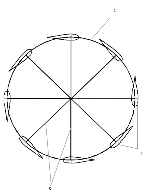
Figure 02
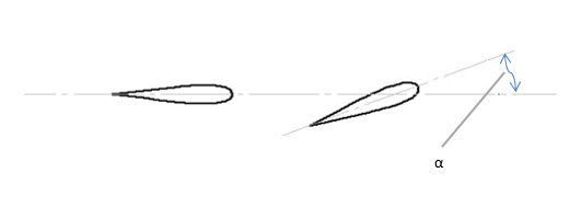
Figure 03

Figure 04
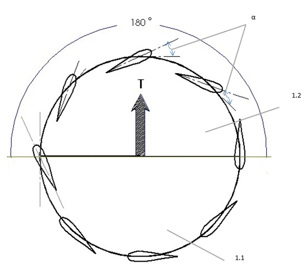
Figure 05
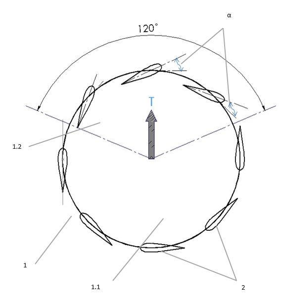
Figure 06
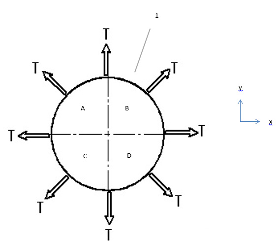
Figure 07
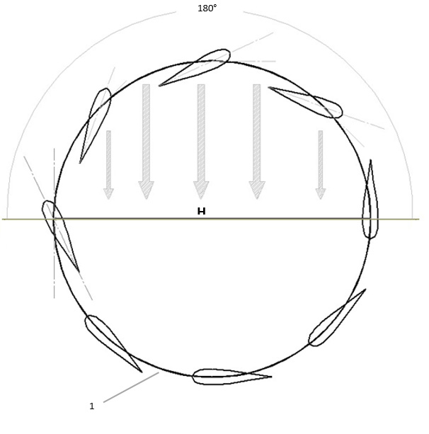
Figure 08
