My dream of designing a personal and light-weight vehicle like the animation on the main page and of achieving a system design that feels comfortable like a part of the body, that has a functional use and that assists us in flying like the birds may be coming true.
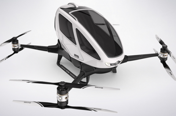
Let’s first talk about the Drones. As known, the Drones are currently in use in many different fields. The first Drone intended for personal use has recently been introduced by a Chinese company. This Drone, weighing 200 kg, has been stated to be capable of carrying an individual for 20 minutes. Given the name EHANG 184, said Drone is able to be controlled by means of a tablet and includes four sets of electric motors.
While these studies are very nice, we of course know that these vehicles, which operate based on the logic of operation of an helicopter, require considerable power due to their small wing diameters and that the weights of the electric motor coils and the batteries required for the operation significantly affect the overall weight of the system, hence the carrying capacity. On the other hand, we are pleased with a small-scale personal air vehicle, the development of such alternative vehicle that would let us experience the pleasure of flying and the possibilities it would provide for us regarding the personal experience of flying pleasure.
However, my aim is to develop the concept of a vehicle that is even smaller, lighter, more portable and more personal (like a bicycle, scooter, paramotor) and that feels like a part of the individual. For this, a design with high efficiency, that is, one requiring less power and being rather light-weight, is necessary. The efficiency of the helicopters – efficiency of the aircrafts and the efficiency of the cyclogyro systems were described and a comparison in terms of efficiency was made with the cyclogyro/cyclocopter design on the “PRESENTATION” page under the main heading “2009-2010 STUDIES AND OBSERVATIONS”; in other words, the cyclogyro/cyclocopter system design was much more efficient than the helicopters:
Another fact that makes me quite more hopeful is the cyclogyro/cyclocopter-based studies performed by the company D-dallus. Before we pass on to the studies performed by D-dallus;
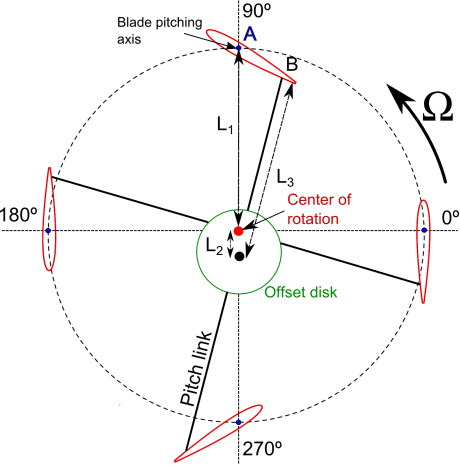
The theoretical studies I conducted in 2010 and the response these studies got in the form of their embodiment in a prototype had made very happy and had given me hope. To briefly and rapidly recollect the cyclogyro/cyclocopter and cycloidal rotor system, the details for which are described under the respective headings “prototype study” and “operating principles of the system”, the following Figure:1 and animation:1 will be of assistance to us;

Figure :1
Animation : 1
As will be understood from the above figure and animation, the wings assume different angles of incidence at every point of the cyclic motion in the cycloidal rotor system. As shown in the figures, while the wings assume a positive angle of incidence in one half of the rotational axis, they assume a negative value for the same in the other half of the rotational axis.
Yes, the power calculations I made on the basis of this theory as well as the values measured in my prototype studies had matched one another and had shown that my hope was not vain. Some studies I have seen on the internet environment after a period of about six years, the fact that the theoretical background for these studies are the same as that for my studies and the certain level achieved by these studies in progress have given me even greater hope, stiffened my belief and encouraged me. A brief summary of the studies conducted by the company D-Dallus is as follows;

The company D-Dallus caused a weight of 100 kg to take off via the concept seen in the animation above. Said concept seen in the video operates based on the same principle of cycloidal rotor for which I had performed the prototype studies in 2009-2010.
As a result, the studies performed by the company D-dallus match up with my studies and support my findings. It is highly likely that my past experiences and observations as well as my impressions from the studies of the company D-dallus and my novel manner of approach will allow the design of a vehicle that is more feasible and is capable of more stable operation.
NOW, MY NOVEL MANNER OF APPROACH
During my prototype studies in 2009-2010, the system was confirmed to be efficient. However, the fact that the wing continuously assumed different angles on the rotational axis as a matter of operating principle of cyclogyro/cyclocopter was noted to have a considerable adverse effect on the stability of the system. This is observed to a certain extent also in the studies by the company D-dallus as far as understood from the images on the internet environment. At this point, I have adopted a novel manner of approach, which I believe would enable us to resolve the stability issue more easily. According to this manner of approach, the wings are to perform the active, real work only during the half of the cyclic motion, while assuming an inactive/neutral state during the other half. In this manner, even though the efficiency of the system is partially reduced, it could still be quite efficient compared to the helicopters and besides, the mechanism of the system and the control system could be simpler and lighter and the vehicle could have the ability of flying much more easily and of being controlled much more easily;
Here are the details of my novel manner of approach:

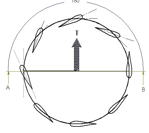
Figure : 1

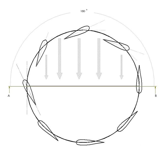
Figure : 2
In Figure : 1, the positions at non-zero angles assumed by the wings during their cyclic motion along the upper semicircle (in a 180-degree cycle) of the section AB are shown and the direction of the lift corresponding to these positions of the wings is indicated.
In Figure : 2, the direction of the air flow is shown schematically again in a cyclic angular motion of the wings along the upper semicircle of the section AB. Here the wings perform real work and try to lift up the system while pushing the air downwards in the direction indicated by the arrows.
The visual animation would be as follows for the system attempted to be explained above with the aid of Figure : 1 and Figure : 2. The wings would be provided with angular positions to the extent we prefer in order to enable them to perform effective work during a half period for each cycle.


