The present invention relates to an engine and system for moving and directing an air vehicle, which enables the air vehicles to move.
1. Description of the Figures
1. The detailed side view of an engine for moving and directing an air vehicle
2. Side sectional view of the wing symmetrical structure
3. Top transparent view of the wing structure
4. The view of the wing structure, in which the moment center is seen
5. The top transparent view of the wing structure, in which the bearing handle and wing moment center are seen
6. The top view of an engine for moving and directing an air vehicle, wherein the wings are zero degree against the rotating axis
7. The top view of an engine for moving and directing an air vehicle on the move, in which the center point of the wing tail circle is shifted and in another position (M’ position)
8. Top view showing the kinematic forces of an engine for moving and directing an air vehicle when it is on the move
9. View showing the kinematic forces of the engine for moving and directing an air vehicle for unsymmetrical wing angles
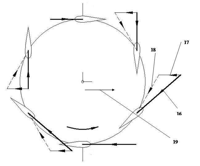
10. The top view of an engine for moving and directing an air vehicle together with velocity vectors on the move
Description of the Parts
1. Shaft
2. Drum
3. Wings
4. Bearing point
5. Drum center
6. Wing tail
7. Wing head
8. Wing moment center
8.1. The moment center of the wing front surface
8.2. The moment center of the wing back surface
9. The tangent circle of the wing tails in stabilized position
10. The tangent circle with a M’ center that the wing tails form
11. Total buoyancy force
12. Buoyancy Force
13. The component of the x axis of the buoyancy force
14. The component of the y axis of the buoyancy force
15. The rotation direction of the drum
16. The resultant speed on the wing
17. The speed of the system
18. Circular rotational speed of the wing
19. Direction of the system
M. The central point of the wing tail circle
M´. The shifted central point of the wing tail circle
The engine for moving and directing an air vehicle according to the present invention can take off and land vertically and can also hang in the air. Therefore for the air vehicles with fixed wings, there is no need to use long and smooth airstrips which are obligatory for these vehicles to take off.
Since the engine for moving and directing an air vehicle does not have complicated structures like those of helicopters etc., their production and consumption costs are much lower. Moreover thanks to their simple structure, their potential to break down is lower compared to the helicopters and so forth. Furthermore, helicopters and so forth are the systems whose maneuver capability is limited, however the present invention is more advantageous compared to the helicopters and so forth in terms of maneuver capability.
With the usage of the engine for moving and directing an air vehicle according to the present invention, unit vehicle mass/capability to carry ratio decreases (for an air vehicle made of appropriate composite materials).
With the usage of the engine for moving and directing an air vehicle according to the present invention, when the efficiency rate is compared with the helicopter and so forth, it increases up to 100%.
With the usage of the engine for moving and directing an air vehicle according to the present invention, it is made possible to carry people by means of air vehicle systems of low-weight and simple structure (low-cost). Therefore, it becomes possible to produce air vehicles which can take off vertically and which can be used in daily life and individually.
Since the engine for moving and directing an air vehicle according to the present invention can control the force, which provides the movement, on a 360º-plane, the maneuver capability of the system increases more compared to the available air vehicles.
The engine for moving and directing an air vehicle according to the present invention can be designed in such a way that they will make a sound less than the available systems do, depending on the sound insulations and force unit to be utilized. For this reason they are appropriate to be used in combat air vehicles which are desired to operate with no sound.
Since the wings of the engine for moving and directing an air vehicle according to the present invention are embedded from both of the edges, the problems related to stabilization experienced in some air vehicles such as helicopter etc. are eliminated. With the help of the said embedded wings, the wing-edge whirlpools, the inefficiency resulting from that situation and the stabilization-destroying effect of this situation are eliminated.
The engine for moving and directing an air vehicle according to the present invention, comprises a shaft (1), at least two circular drums (2) positioned on the said shaft (1), preferably on the two opposite edges of the said shaft (1) with desired distance to each other. When requested, wing-carrying handles can also be used within the systems instead of the drums. Preferably reciprocal wings (3) are located on the outer borders of the the drum (2) with equal distance to each other. Each wing (3) is connected to the drums (2) located on the shafts (1) by means of bearing points (4). The distance of each bearing point (4) on the drum (2), in other words the distance of each wing (3) to the center of the drum (5) is stable.
The drums (2) located on the shafts (1) and the wings (3) embedded on the drums (2) can be produced from various materials such as wood, metal, alloy, composite and the like. However, the lightest and the strongest material should be chosen in order to provide flight stabilization and efficiency.
Preferably the structure of the wings (3) should have symmetrical cut view. The upper cut view of the wing (3) and the bottom cut view of the wing (3) are the same according to the A-B axis. However the preferable wing (3) form should be chosen from NACA Airfoil or the other various symmetry forms.
The length, width and thickness of the wing (3) may change depending on their area of usage. Different wing (3) length, width and thickness values can be used for different areas of usage and for different purposes so as to generate different thrust and tractive force. Likewise, the number of the wings to be used within the system can be arranged so as to generate the desired thrust force.
While the wings (3) are embedded to the drums (2), they are preferably embedded through the moment center (8) of the wing. The moment center of the wing (3), is preferably located on the part which is closer to the wing head (7). When the width of the wing (3) is considered as a variable such as “c”, preferably the distance of the moment center (8) of the wing to the wing head (7) is c/4, and its distance to the wing tail (6) is 3c/4. The wings (3) on the drums (2) are preferably embedded at the reciprocal sides through the said moment centers (8) of the wing.
The wings (3) which are embedded on the drums (2) from the moment centers (8) of the wings as stated above, can be directed in a way that they will make a (+) and (-) angle around the same axis depending on the directing amount and direction. Therefore the wings can independently move, so that they can make a (+) and (-) angle around the wing moment center.
When the engine for moving and directing an air vehicle according to the present invention is in a stabilized position, all of the wings (3) make a 0 degree angle to the rotational axis. When the wings (3) make a 0 degree angle to the rotational axis without changing the angles of the wings (3), and then when movement is generated on the drum (2), the wings (3) which move in circular directions do not generate thrust and tractive force since the wings (3) move by making a 0 degree angle of attack against the rotational axis.
While the wings (3) embedded on a certain radius are rotating with the drum (2), the circle defined by the drum (2) determines the wing moment axis and it is always on the same route without any change. During this movement of the system, the wings (3) move with a 0-angle of attack, and in this case, the stabilized position of the wing tails tangent circle (9) center which is assumed to pass through the wing tails (6), becomes the central point (M) of the wing-tail circle. Although the drum (2) rotates, during the said movement, the system does not operate because the angle of attack is zero and thus the thrust-tractive force is zero.
In order to generate thrust and tractive force as a result of the movement of the system, it is needed to shift the central point (M) of the wing-tail circle which is the center of the tangent circle (9) of the wing tails on a stabilized position, which is thought to pass through the wing-tails (6). Therefore, the total vectoral forces acting on the system provide a thrust and tractive force. When the central point (M) of the wing-tail circle is shifted (if it is moved to a new position called M’), the sizes of the circle that the wing tails (6) have formed do not change but only the position of the circle, and therefore the point on which the center of the circle is located changes.
For example as a result of an any kind of an effect on the system, when the central point (M) of the wing tail circle where the wing tails (6) are thought to pass through, and the shifted central point (M’) of the wing tail circle are desired to be shifted, the wing attack edges can be arranged in different sizes so that they will have (+) and (-) values depending on different positions. While the drum (2) and therefore the wings (3) are rotating anti-clockwise, the wings (3) on the left of the CD axis have (-) angles of attack of different sizes whereas the wings (3) on the right of the CD axis have (+) angles of attack again of different sizes. Thus the wings (3) start to generate vectoral force depending on the angle of attack that they make based on their position and the instant resultant speed at this point.
Each wing (3) applies a buoyancy force (12) to the system as a result of its own movement. In order to calculate the total instant vectoral force, x axis components (13) of the buoyancy force applied by each wing (3) and the y axis components (14) of the buoyancy force need to be summed up. By summing up the said vector components, the total instant vectoral force and therefore the total buoyancy force (11) can be obtained. The total buoyancy force (11) is the buoyancy force applied by the wings (3) to the system for instant wing (3) positions. If the center of the wing tails (6) that we have positioned is chosen as the central point (M’) whose wing tail circle is shifted, the direction of the total buoyancy force (11) is on (+) direction at the x axis. The size of the total buoyancy force (11) that we have obtained can be controlled by some variables such as the structure of the wing (3), the number of the wing (3), the rotational speed, and the distance between the central point (M’) whose wing tail circle is shifted and the central point (M) of the wing tail circle, wherein the said variables can be adjusted by the user himself/herself.
As is mentioned above in the vectoral analysis part, in the case that the central point (M) of the wing tail circle is shifted to a position at the x axis and (-) direction just like the central point (M’) whose wing tail circle is shifted, the total buoyancy force (11) effecting the system is effected on the opposite way, that is at the x axis plane and (+) direction. Again when the central point (M’) whose wing tail circle is shifted to the (+) direction on the y axis which is a different point, the total buoyancy force (11) is going to affect the system in the (-) direction on the y axis. By making use of this basic principle, the direction and the size of the total buoyancy force (11) affecting the system can be adjusted by changing the place of the central point (M) of the wing tail circle.
The magnitude of the buoyancy force (12) generated by each of the wings (3) within the system is proportional to the speed of the said wing (3) at that position and at that moment. The instant speed of a wing (3) rotating together with the drum (2) on a moving system is expressed as the resultant speed (16) on the wing. The said speed vector consists of two speed vectors: the speed of the system (17) and the circular rotation speed (18) of the wing. The speed of the system (17) is under the effect of some variables such as the rotational speed of the drum (2), that is the rotational speed (18) of the wing, the rotational direction of the drum (15), and the movement direction (19) of the system and the speed of the system (17).
Within the system for moving and directing an air vehicle described above, the direction and the magnitude of the force affecting the system, therefore the movement direction of the system and its speed on this direction can be adjusted by putting the central point (M) of the wing tail circle on various positions on a 360-degree plane. In this case the central point of the circle which is thought to pass through the wing tails (6) changes and as a result, the resultant of the forces affecting the wings (3) changes as well.
In order for the central point (M) of the wing tail circle which is thought to have been formed by the wing tails (6) to change the position of the central point of the centered circle, the direction and angles of the wings (3) on the drum (2) can be arranged by means of a kind of overall directing apparatus and therefore a force of desired direction and desired magnitude and then a movement of desired direction and of desired speed can be generated.
In order for the above-mentioned movement and direction system to be designed, the wings (3) need to be positioned on the drum (2) symmetrically. The said symmetrical wing positions and locations enable the vectoral magnitudes generated on the instant positions of the wings to be closer to symmetry. By this means, the movement mechanism of the system becomes simpler and more controllable. However the wing (3) locations and positions can be used depending on the same principle in the anti-symmetrical systems. In this case more careful calculations should be done while making analysis about the magnitude and direction of the total buoyancy force (11).
According to the preference, the system can be operated with a single drum (2) located on a shaft (1) or with more than one single drum (2) as well. In the systems with one single drum (2) just like in the systems with more than one drum (2), the wings (3) are preferably embedded on the drum (2) from the bearing points (4) reciprocally and with equal distance.
The movement of the engine for moving and directing an air vehicle according to the present invention is provided by means of a drive unit connected to the system. The said drive unit regulates the amount of movement generated by changing the rotational speed of the system.
CLAIMS
1. An air movement and direction engine that can be used in the air vehicles, characterized in comprising a shaft (1), two drums (2) preferably in circular structure which are positioned on the said shaft (1), preferably on two different tips of the shaft with desired distances to each other, and wings (3) which are preferably positioned opposite to each other.
2. The drum (2) according to Claim 1, characterized in that wing-carrying handles can also be used instead of drum.
3. The wing (3) according to Claim 1, characterized in that each of the wings (3) is connected to the drums (2) located on the shaft, by means of bearing positions (4).
4. The bearing point (4) according to any of the preceding Claims, characterized in that the distance of the bearing point (4), and therefore the distance of each wing (3) to the center of the drum (5) is the same.
5. The wings (3) according to Claim 1, characterized in that the upper cut view of the wing (3) and the bottom cut view of the wing (3) are symmetrical to the A-B axis.
6. The wings (3) according to Claim 1, characterized in that different number of wings, different wing width, different wing length and different wing thickness can be used for different fields and purposes.
7. The wings (3) according to Claim 1, characterized in that the wing moment center (8) is embedded preferably to a position close to the head of the wing (7) while it is embedded to the drums (2).
8. The wing moment center (8) according to the preceding claims, characterized in that in one embodiment of the present invention when the wing (3) width is a variable like “c”, the distance of the wing moment center (8) to the head of the wing (7) is c/4, whereas the distance of the wing moment center (8) to the wing tail (6) is 3c/4.
9. The wings according to Claim 1, characterized in that while the wings (3) are embedded to the drums (2), they are embedded from the wing moment centers (8) preferably in reciprocal positions.
10. The wings (3) according to Claim 1, characterized in that the wings (3) embedded from the wing moment centers (8) on the drums (2) can be directed in such a way that they will make an (+) and (-) angle around the axis of the wing moment center (8) depending on the amount of direction and the direction itself.
11. An air movement and direction engine that can be used in air vehicles, characterized in that the drum (2) and the wings (3) positioned on the shaft are made of some materials such as wood, metal, alloy, composite etc.
12. An air engine according to the preceding claims, its operation principle is characterized as follows:
• When the engine for directing and moving an air vehicle according to the present invention is in a stabilized position, all of the wings (3) make a 0-degree angle against the rotational axis,
• When a movement is provided on the drum (2) in the case that the wings (3) make a 0-degree angle against the rotational axis without changing the angles of the wing, the wings (3) move by making a 0-degree angle of attack against the rotational axis of the wings (3) and therefore the wings moving in circular direction do not generate thrust or tractive force,
• While the wings (3) embedded on a certain radius are rotating together with the drum (2), the circular axis of the wing moment is determined by the drum and it goes on rotating on the same route always, and therefore the center of the tangent circle (9) of the wing tails (6) in a stabilized position becomes the central point (M) of the wing tail circle,
• The central point (M) of the wing tail circle which is the central point of the tangent circle (9) of the wing tails in a stabilized position which is thought to have passed through the wing tails (6), is shifted and therefore the total vectoral forces effecting the system generate a thrust and tractive force,
• By directing the wing angles at first, when a movement is generated on the drum (2) following the first stable position where the wings (3) attain different (-) and (+) positions depending on the rotational axis, the wings (3) can move by attaining different angle values depending on the rotational axis, wherein in order to achieve an effective thrust-tractive force, the number of turnover of the drum (2) can be controlled by means of a drive-unit,
• When the central point (M) of the wing tail circle is shifted to a central point (M’) whose wing tail circle is shifted, the wing attack edges are arranged so that they will get (-) and (+) values in different magnitudes depending on different locations, and then while the wings (3) are rotating anti-clockwise the wings on the left of the CD axis make (-) attack angles in different magnitudes and the wings (3) on the right have (+) angle of attack values again in the same magnitude, and then vectoral forces are generated depending on the position of the wings (3) and the angle of attack that they make based on their position and the instant resultant speed at this point,
• When the central point (M) of the wing tail circle is shifted to the central point (M’) whose wing tail circle is shifted, the said vectoral forces and therefore the vector of buoyancy forces are generated for each wing,
• When the central point (M) of the wing tail circle is shifted to the central point (M’) whose wing tail circle is shifted, at the x axis and (-) direction, the vector of the total buoyancy force (11) is on the x axis and (+) direction, and the magnitude of the said total buoyancy force (11) can be controlled by some variables such as the structure of the wings (3), the number of wings (3), rotational speed and the distance between the central point (M) of the wing tail circle and the central point (M’) whose wing tail circle is shifted, and it can be adjusted by the user himself/herself,
• Likewise when the central point (M) of the wing tail circle is shifted to the central point (M’) whose wing tail circle is shifted, on the x axis and (+) direction, the vector of the total buoyancy force (11) is on the x axis and (-) direction and then by putting the central point (M) of the wing tail circle to various positions on a 360-degree plane, the direction and the magnitude of the buoyancy force (11) are adjusted,
• By adjusting the direction and magnitude of the buoyancy force (11), the movement direction and speed of the system can also be adjusted.
13. An air movement and direction engine operating with the operation principle stated above, characterized in comprising a kind of overall direction apparatus making the angles in the desired directions and of the desired magnitude in order to change the central point (M) of the wing tail circle of the tangent circle (9) of the wing tails (6) in a stabilized position which is thought to have been formed by the wing (3) tails, into the position of the central point (M’) whose wing tail circle is shifted; and in order to enable the wings (3) on the drum (2) to be directed.
14. An air movement and direction engine according to the preceding claims, characterized in that it can be used together with wing (3) arrangements located on anti-symmetrical positions.
15. An air movement and direction engine, characterized in comprising one or more drums (2) on a shaft.
16. An air movement and direction engine, characterized in that the movement of the shaft (1) and then the drum(s) (2) can be provided by means of a drive unit to be connected to the system.
Figure 01
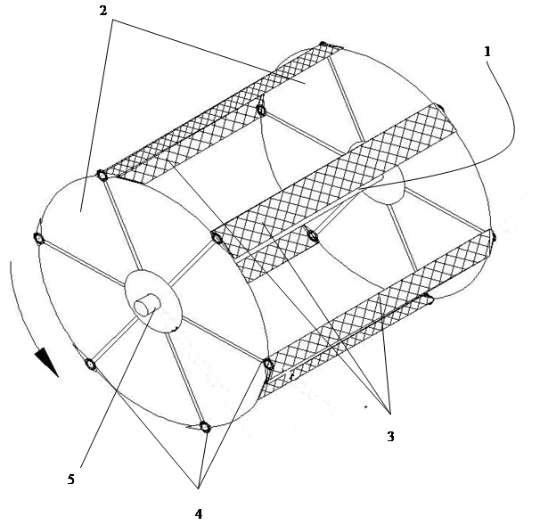
Figure 02
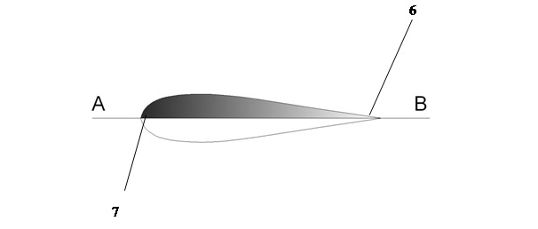
Figure 03

Figure 04

Figure 05
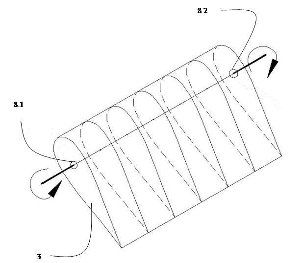
Figure 06
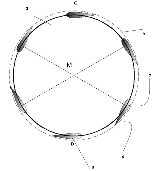
Figure 07
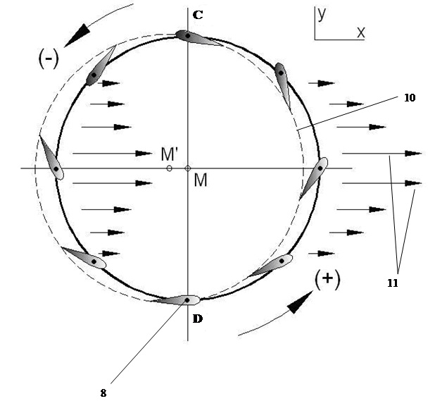
Figure 08
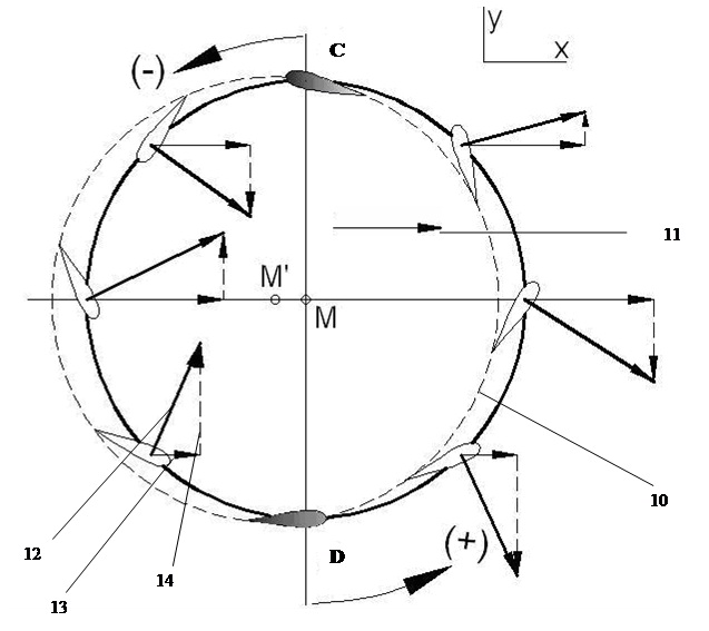
Figure 09
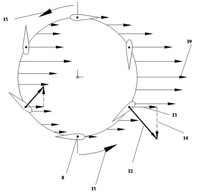
Figure 10
